ASSEMBLY
OM 0313QH-A 11
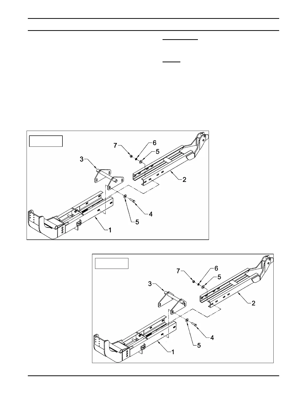
Figure 2b
3. (FIGURE 2a or 2b) Assemble the rear
subframe (item 2), the front subframe (item
1) and the mid support (item 3) using four
3/4"NC x 2 3/4" bolts (item 4), 13/16"
flatwashers (item 5), 3/4" lockwashers (item
6) and 3/4"NC nylon insert locknuts (item
7). Assemble according to figure 2a for
tractor models L3130, L3430 and L3830
and according to figure 2b for tractor
models L4330, L4630 and L5030.
IMPORTANT: Make sure the mid support
(item 3) is assembled as indicated on figure
2a or 2b.
NOTE: Do not tighten the four 3/4"NC x 2
3/4" bolts (item 4) until the subframe is well
positioned under the tractor.
 Loading...


