ENGINE
DIESEL PARTICULATE FILTER HANDLING MANUAL, WSM
1-S22
[10] ASSEMBLY OF DPF MUFFLER FULL ASSEMBLY
(1) D1803-CR-E4, D1803-CR-TE4, V2403-CR-E4, V2403-CR-TE4
• Visually check if there is no damage (ceramic crack or damage) with the cleaned and returned DPF filter
complete.
DOC Catalyst Complete, DPF Filter Complete and DPF Outlet
Body
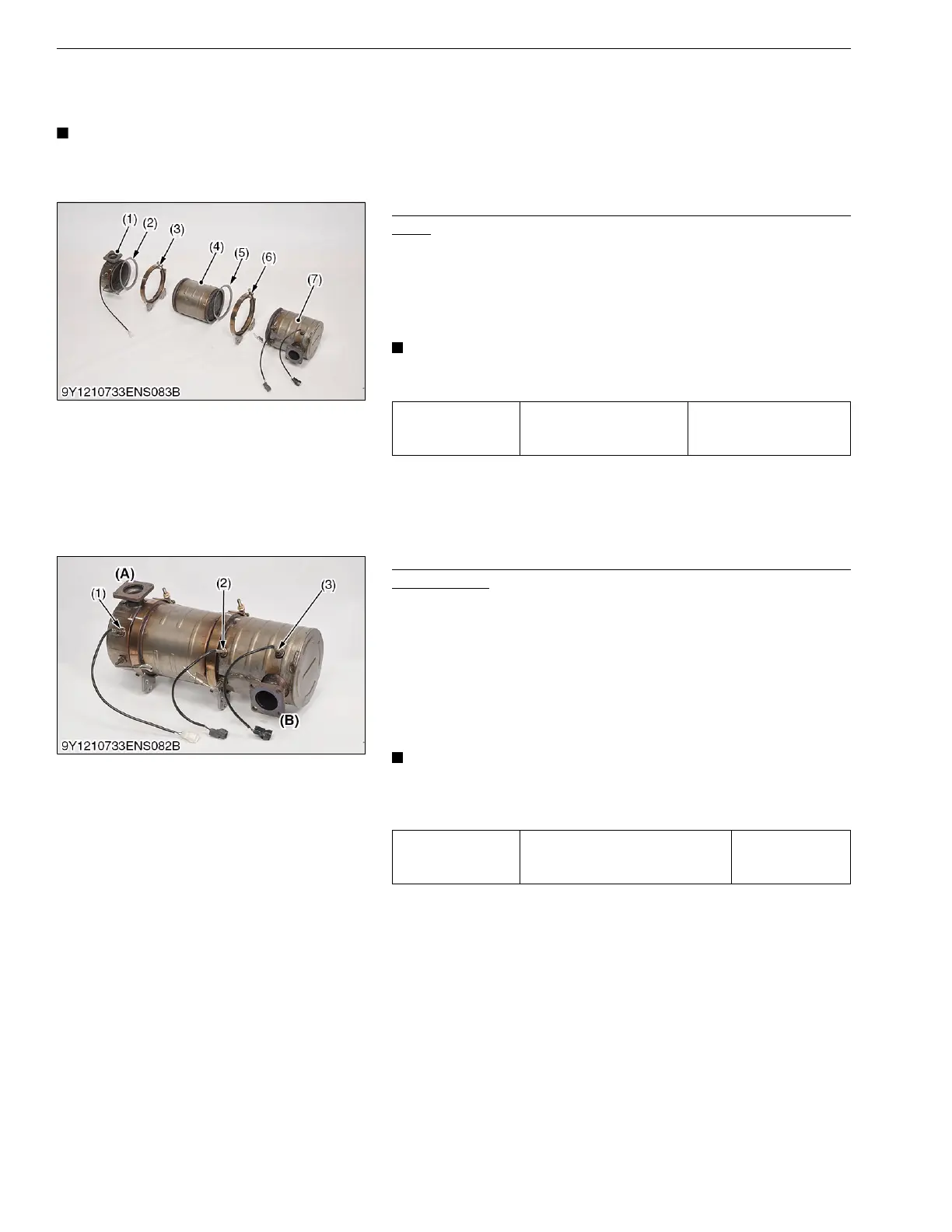
1. Replace the gaskets (2), (5) with new ones.
2. Clean the mounting surface of each flange.
3. Assemble the DOC catalyst complete (7), DPF filter complete
(4), and DPF outlet body (1) with DPF mounting clamp band (3),
(6).
• Assemble the DPF filter complete (4) in the correct
direction.
Exhaust Temperature Sensor (In the event of need for
replacement)
When the exhaust temperature sensor is removed or has to be
replaced because it is damaged, follow the procedure given below.
1. Clean the screw parts and apply anti seize agent (NEVER
SEEZ made by Bostik, Grade: Pure nickel special grade).
2. Install the exhaust temperature sensor T0 (3), T1 (2), and T2 (1)
from the exhaust inlet side (catalyst complete side) sequentially.
3. Install each exhaust temperature sensor with the specified
torque.
• Anti seize agent is already applied to the screw parts of
new exhaust temperature sensor.
So, it is not necessary to apply it when replacing new ones.
Tightening torque DPF mounting clamp band
16 to 20 N·m
1.7 to 2.0 kgf·m
12 to 14 lbf·ft
(1) DPF Outlet Body
(2) Gasket
(3) DPF mounting clamp band
(4) DPF Filter Complete
(5) Gasket
(6) DPF mounting clamp band
(7) DOC Catalyst Complete
Tightening torque
Exhaust temperature sensor T0
Exhaust temperature sensor T1
Exhaust temperature sensor T2
25.0 to 35.0 N·m
2.55 to 3.56 kgf·m
18.5 to 25.8 lbf·ft
(1) Exhaust Temperature Sensor T2
(White Connector: 1J801-18520)
(2) Exhaust Temperature Sensor T1
(Gray Connector: 1J500-18510)
(3) Exhaust Temperature Sensor T0
(Black Connector: 1J500-18500)
(A) Exhaust Outlet Side
(B) Exhaust Inlet Side



 To Next Page