Do you have a question about the KYMCO agility R16 150 and is the answer not in the manual?
| Displacement | 149.5 cc |
|---|---|
| Bore x Stroke | 57.4 mm x 57.8 mm |
| Compression Ratio | 10.0:1 |
| Fuel System | Carburetor |
| Ignition | CDI |
| Transmission | CVT |
| Front Suspension | Telescopic fork |
| Front Brake | Disc |
| Rear Brake | Drum |
| Front Tire | 100/80-16 |
| Rear Tire | 120/80-16 |
| Wheelbase | 1340 mm |
| Seat Height | 780 mm |
| Engine Type | 4-stroke |
| Starting System | Electric & Kick |
Identifies the engine's unique serial number for tracking.
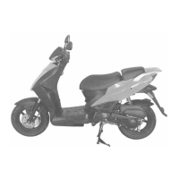
Provides detailed technical specifications for the motorcycle.
Outlines essential safety and procedural precautions for servicing.
Lists critical torque specifications for fasteners during assembly.
Identifies specialized tools required for specific maintenance tasks.
Details specific points requiring lubrication for engine and frame.
Illustrates the routing paths for cables and wire harnesses.
Presents the complete electrical system wiring diagram.
Guides users through diagnosing and resolving common engine starting issues.
Provides an exploded view of frame cover and exhaust components.
Offers general instructions and warnings for servicing frame covers.
Details the procedure for removing front, handlebar, and met-in box covers.
Outlines the steps for removing floor board, front fender, and leg shield.
Provides instructions for removing the exhaust muffler and its components.
Provides general guidance and safety warnings for inspections.
Lists key specifications for engine and chassis components.
Details the recommended periodic maintenance intervals and tasks.
Covers inspection of the fuel filter and adjustment of throttle operation.
Provides service procedures for the air cleaner and spark plug.
Guides adjustment of valve clearance and carburetor idle speed.
Covers inspection of ignition timing and cylinder compression.
Details service procedures for final reduction gear oil and drive belt.
Outlines checks and adjustments for the front and rear brake systems.
Covers headlight aiming, clutch shoe wear inspection, and suspension checks.
Details inspection of rear suspension, critical fasteners, and wheels/tires.
Describes inspection of the steering handlebar for smooth operation.
Provides general instructions and specifications for the lubrication system.
Guides diagnosis of lubrication system issues like low oil level.
Covers engine oil level check, filter, and oil pump removal procedures.
Details disassembly and measurement of oil pump components.
Illustrates the main components of the fuel system.
Shows the electrical connections related to the fuel system.
Provides general instructions and technical specifications for the fuel system.
Guides diagnosis of fuel system issues like hard starting or misfiring.
Details carburetor removal and auto bystarter inspection steps.
Covers disassembly and assembly procedures for these carburetor components.
Provides instructions for disassembling the carburetor float chamber.
Outlines the steps for correctly installing the carburetor.
Explains how to adjust the pilot screw for idle speed tuning.
Illustrates the overall engine removal process.
Provides general instructions and safety guidelines for engine removal.
Details disconnecting electrical, fuel, and vacuum lines before engine removal.
Outlines the process of removing engine mounting bolts and the hanger bracket.
Guides the installation of the engine hanger bracket and the engine itself.
Provides an exploded view of cylinder head and valve components.
Lists general instructions and technical specifications for cylinder head service.
Details critical torque values and troubleshooting for cylinder head issues.
Guides the user through the process of removing the camshaft.
Covers inspection procedures for the camshaft and its lobe height.
Outlines the steps required to remove the cylinder head.
Details the process of disassembling the cylinder head, including valve springs.
Covers valve inspection and the assembly of the cylinder head.
Details the process of installing the camshaft and related components.
Shows an exploded view of cylinder and piston components.
Provides core technical data and troubleshooting for cylinder/piston.
Details the removal of the cylinder and piston assembly.
Covers piston inspection and the correct installation of piston rings.
Details critical measurements for piston and cylinder inspection.
Covers cylinder warpage checks and piston ring installation procedures.
Provides procedural steps for installing the piston and cylinder.
Shows an exploded view of pulley and kick starter components.
Provides core technical data and troubleshooting for pulleys and kick starter.
Details the service procedures for the left crankcase cover.
Covers drive pulley removal and drive belt inspection procedures.
Details the disassembly process for the clutch/driven pulley assembly.
Provides inspection procedures for kick starter components.
Guides the installation process for the kick starter assembly.
Shows an exploded view of the final reduction gear components.
Provides system overview and troubleshooting for the final reduction.
Covers disassembly and inspection of final reduction gears and shafts.
Details bearing replacement and the assembly of the final reduction system.
Shows an exploded view of crankcase and crankshaft components.
Provides core technical data and troubleshooting for the crankcase/crankshaft.
Details the procedure for separating the crankcase halves.
Covers critical inspection of connecting rod clearance and crankshaft runout.
Details the steps involved in assembling the crankcase.
Shows an exploded view of front wheel, brake, and suspension components.
Provides overview, critical data, and required tools for front end service.
Guides diagnosis of common steering, wheel, and suspension problems.
Details the procedure for removing and installing the steering handlebar.
Covers front wheel removal and axle runout measurement.
Details inspection of wheel rim runout, bearings, and dust seal removal.
Guides the process of assembling the wheel bearings correctly.
Covers front brake fluid replacement, bleeding, and refilling procedures.
Details the steps involved in disassembling the brake caliper.
Covers the removal and disassembly procedures for the front shock absorber.
Guides measurement of the shock absorber spring and its assembly.
Details front fork removal and replacement of steering races.
Shows an exploded view of rear wheel, brake, and suspension components.
Provides system overview and troubleshooting for rear wheel, brake, and suspension.
Covers the procedures for removing, inspecting, and installing the rear wheel.
Details the inspection, disassembly, and assembly of the rear brake.
Covers the removal and disassembly procedures for the rear shock absorber.
Guides the installation process for the rear shock absorber.
Shows the electrical diagram for the battery, charging system, and AC generator.
Provides general information and safety instructions for battery and charging system.
Lists technical specifications and troubleshooting for the system.
Covers battery removal, voltage inspection, and charging procedures.
Details charging system short circuit test and current testing procedures.
Covers inspection and removal procedures for the regulator/rectifier.
Details inspection and removal of the AC generator charging coil.
Provides instructions for the installation of the AC generator.
Shows the electrical diagram for the ignition system.
Provides general information and technical specifications for the ignition system.
Lists common problems and solutions for the ignition system.
Details the procedure for inspecting the CDI unit.
Covers the inspection procedures for the ignition coil.
Guides inspection of the pulser coil and ignition timing.
Shows the electrical diagram for the starting system.
Provides general information and troubleshooting for the starting system.
Covers starter motor removal, disassembly, and inspection procedures.
Details starter relay inspection and voltage checking procedures.
Covers starter clutch removal, inspection, and disassembly.
Provides general instructions and troubleshooting for lights and instruments.
Covers fuel unit removal, installation, and inspection procedures.
Details the inspection procedures for various handlebar switches.
Covers service procedures for the horn switch and ignition switch.
Covers service for stop switches, horn, and instrument cluster.
Details replacement procedures for headlight and rear light bulbs.
Illustrates the components and flow of the exhaust emission control system.
Provides system overview and troubleshooting for emission control issues.
Details the recommended periodic maintenance schedule for the emission system.