•NOTE:
Resistance
tests
should
be
madE~
with
the
connector
disconne
cted and
on
the
seiE1ctor-side
of
the
connector
.
RESISTANCE
~
CAUTION
II
Always disconnect the battery when
pE
!rforming
resistance tests
to
avoid damaging the mul'llmeter.
l. Set the meter selector to the OHMS position.
2.
Connect the one tester lead to the brown/lavender
wire; then connect the other tester lead to the
white/lavend
er
wire.
3. With the selector
s·witch in the 2WD position, the
meter must show less than l ohm.
4. With the sel
ec
tor swit
ch
in
th
e 4WD position,
th
e
meter must show an open circuit.
•NOTE
:
If
the
meter does
not
show
as
!Specified,
replace
the
front
drive
selector
switch.
VOLTAGE
•NOTE
: The battery
must
be connected
when
per-
forming voltage tests.
l. Set the meter selector to the DC Voltage position.
2.
Connect the black tester lead to the
neg~ative
bat-
te
ry
terminal.
3. C01mect the red tester lead to the brown/lavender
wire
on
th
e harness side
of
the connector.
4. Turn the ignition switch to the RUN
posi1tion.
5.
The meter must show battery voltag
e.
•NOTE
:
If
the
meter
shows
other
than
!Spec
ified,
check
the
harness, connector, 30
amp
lfuse, and
battery
connections
.
Front
Drive
Selec1tor
Actuator
•NOTE:
With
the
engine stopped and
th1e
ignition
switch
in the ON
position
, a momentary
"whirring
"
sound
must
be noticeable each
time
thet
selector
switch
is
moved
to
2WD and 4WD. Test
the
switch
,
30
amp
fuse, and
wiring
connections
prior
to
test-
ing
the
actuator
.
•NOTE:
The differential
must
be in
the
unlocked
position
for
this
procedure.
5-8
VOLTAGE
l.
Select
th
e 2WD position
on
the front dri
ve
selector
switch; then disconnect the connector on the actu-
ator wiring harness.
2. With the ignition switch in the
OFF position, con-
nect the black tester lead
to
the black wire in the
supply harness; then connect
th
e red tester lead
to
the brown/lavender wire
in
th
e supply harness.
3. Turn the ignition switch to the ON position.
Th
e
meter must show
12
DC volts.
4.
Connect the red tester lead
to
the white/blue wire
in the supply harness. The meter must show
12
DC
volts.
5.
Select
th
e 4WD position on the front drive selector
switch; then connect the red tester lead to the
white/blue wi
re
in the supply harness. The meter
must show
0 DC volts.
•NOTE
: The 4WD
icon
on
the LCD
should
illumi-
nate.
6.
Connect the red tester lead
to
the brown/lavender
wire in
th
e supply harness. The meter must show
12
DC volts.
•NOTE
:
If
the
voltage readings are as specified
and
the
actuator
does
not
function
correctly,
replace
the
actuator
(see Section 6).
Gear
Shift
Position
Svvitch
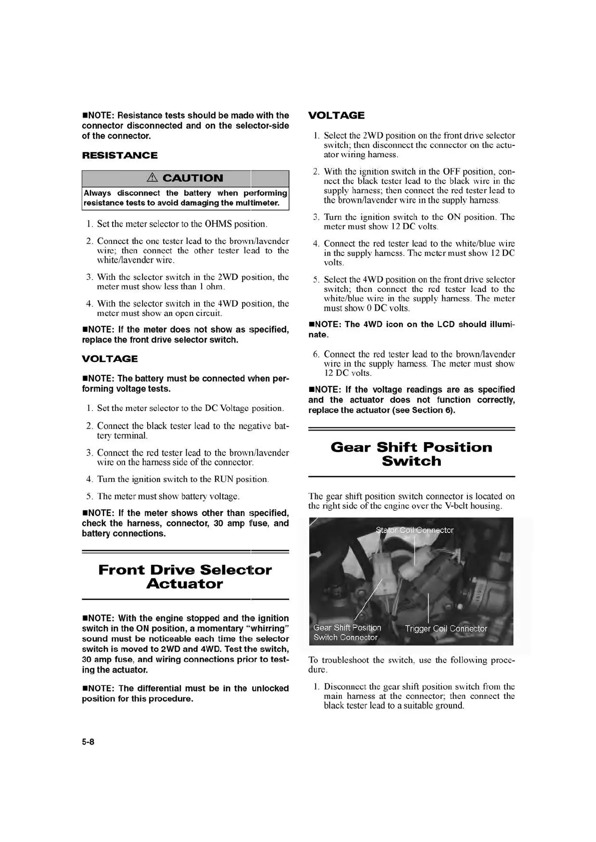
The gear shift position switch connector is located
on
the right side
of
th
e engine over
th
e V-belt housing.
To
troubleshoot the switch, use the following proce-
dure.
l.
Disconnect the gear shift position switch from the
main harness
at
the connector; then connect the
black test
er
l
ea
d to a suitable ground.