Do you have a question about the Kyocera P7240cdn and is the answer not in the manual?
This document outlines a service bulletin for Kyocera devices, addressing a common issue related to dust accumulation and its impact on the LSU (Laser Scanning Unit) drive part, leading to C4600 service call errors. The bulletin provides detailed procedures for field measures, including cleaning, filter installation, and, if necessary, replacement of the LSU drive unit.
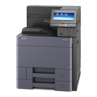
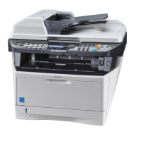
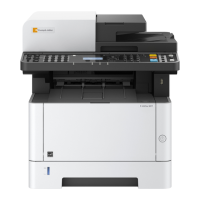
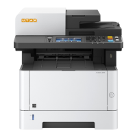
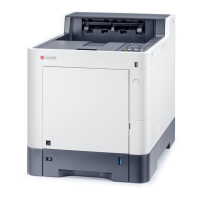
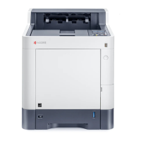
The Kyocera devices covered by this bulletin are designed for printing and multifunction operations, including models such as P7240cdn, P6235cdn, M6635cidn, and TASKalfa 351ci. A critical component within these devices is the LSU, responsible for precisely directing laser beams to form images on the photoconductive drum. The LSU drive unit ensures the proper movement and operation of the LSU, which is essential for high-quality print output. The device's design incorporates louvers on the left side of the main unit, allowing for air circulation necessary for cooling internal components.
The devices are designed for robust and consistent performance in various office environments. However, the bulletin highlights a specific vulnerability: the ingress of dust through the left-side louver. This dust can accumulate on the LSU drive part, increasing the rotation torque of the LSU cleaning motor. When the device performs its routine LSU slit glass cleaning, this increased torque can trigger a C4600 error, indicating an LSU cleaning motor malfunction. This issue can disrupt normal operation, requiring intervention to restore functionality. The devices are equipped with internal diagnostics that detect such errors, prompting a service call to address the underlying problem.
The service bulletin details a comprehensive set of maintenance procedures to prevent and resolve the C4600 error. These procedures are categorized into initial field measures and ongoing maintenance.
Cleaning: The first step involves thoroughly cleaning the area around the louver on the middle left cover and lower left cover. This removes existing dust that could contribute to the problem. The procedure specifies detaching the middle left cover and lower left cover for access, emphasizing the importance of cleaning both the inner and outer sides of the machine around the louver. Alcohol is recommended for cleaning the louver area on the outer side of the main unit.
Filter Installation: To prevent future dust accumulation, dust filters (No1) are installed over the louvers. This involves attaching filter mounting holders (No2) using double-sided tape (No3). The bulletin provides precise alignment instructions for affixing these holders to both the front and rear side louvers, ensuring proper coverage and adherence. The dust filters are then inserted into these holders.
LSU Drive Unit Check and Replacement: If the LSU drive unit (No4 or No5) is already affected by dust accumulation to the point where cleaning is difficult or ineffective, the bulletin recommends checking its condition and replacing it if necessary. While not mandatory, replacement is suggested due to the difficulty of removing internal dust from the unit.
Dust Filter Cleaning/Replacement: After the initial installation, the dust filters (No1) should be cleaned or replaced during subsequent customer visits. The standard replacement interval is one year, but this can vary depending on the installation environment and the level of dust exposure. A vacuum cleaner is suggested for cleaning the dust filter.
Filter Mounting Holder Check: During maintenance, the filter mounting holders (No2) should be checked to ensure they are still securely attached. If any holder is coming off, the double-sided tape set (No3) should be used to re-secure it.
The bulletin also provides a detailed, step-by-step procedure for replacing the LSU drive unit, which is a more involved maintenance task:
Disassembly: This begins with detaching various external covers and internal units, including the upper right, middle right, upper left, and middle left covers, as well as two LSUs, the primary transfer unit, four drum units, and four developer units. This extensive disassembly provides access to the LSU drive unit.
FFC Detachment: Three parts securing the FFC (Flexible Flat Cable) are released, and the FFCs are detached.
Motor Wire Disconnection: The connector of the LSU cleaning motor wire (red) is disconnected from the YC26 connector on the engine relay PWB.
LSU Drive Unit Release (Lower Hooks): Four hooks on the lower side of the LSU drive unit are released in a specific order (1 to 4) to detach it from the metal plate.
LSU Drive Unit Release (Upper Hooks): Four upper side hooks are released, also in a specific order, while ensuring the lower hooks remain released.
LSU Drive Unit Removal: The LSU drive unit is pulled towards the center of the main unit, and the LSU cleaning motor wire is pulled out through a hole on the left frame. It's noted that the LSU drive unit cannot be fully removed at this stage due to the connected FFC.
Cover Duct Left Release: Four hooks of the COVER DUCT LEFT are released from the rear side of the main unit (LSU cleaning motor side) in a specific order (1 to 4), and the COVER DUCT LEFT is detached.
FFC Terminal Disconnection: The FFC terminal is disconnected from the FFC connector on the drum relay PWB.
New LSU Drive Unit Preparation: The COVER DUCT LEFT of the new LSU drive unit is detached, mirroring step 7.
FFC Terminal Connection: The FFC terminal is passed between the DUCT COVER INNER of the new LSU drive unit and the edge of the drum relay PWB, then connected to the FFC connector on the drum relay PWB.
Cover Duct Left Reattachment: The COVER DUCT LEFT is reattached to the new LSU drive unit.
Motor Wire Routing: The LSU cleaning motor wire is passed through the hole on the left frame of the main unit.
LSU Drive Unit Positioning: Two positioning bosses on the LSU drive unit are inserted into two corresponding positioning holes on the left frame of the main unit.
LSU Drive Unit Insertion (Upper Hooks): Four upper hooks are inserted in a specific order (1 to 4).
LSU Drive Unit Insertion (Lower Hooks): Four lower hooks are inserted in a specific order (1 to 4). A cautionary note advises pressing the root of the hook to insert it into the hole on the metal plate, as the hooks can break easily.
Motor Wire Reconnection: The wire connector of the LSU cleaning motor is reconnected to the YC26 connector of the engine relay PWB.
FFC Re-securing: Three parts are reattached to secure the FFC.
Reassembly: Finally, all external covers and units that were detached in step 1 are reattached.
The service bulletin emphasizes that these procedures are designed for authorized Kyocera engineers, highlighting the complexity and precision required for proper maintenance and repair. The provision of specific part numbers for dust filters, mounting holders, double-sided tape, and LSU drive units ensures that the correct components are used for effective resolution of the C4600 error.
| Functions | Print, Copy, Scan, Fax |
|---|---|
| Print Resolution | 1200 x 1200 dpi |
| Duplex Printing | Yes |
| Scan Resolution | 600 x 600 dpi |
| Copy Resolution | 600 x 600 dpi |
| Fax Speed | 33.6 kbps |
| Processor Speed | 1.2 GHz |
| Control Panel | 7-inch Color Touch Screen |
| Operating System Compatibility | Windows, Mac OS, Linux |
| Print Technology | Laser |
| Standard Paper Capacity | 500 sheets |
| Maximum Paper Capacity | 2, 100 sheets |
| Supported Paper Sizes | A4, A5, A6, B5, Legal, Letter |
| Scanner Type | Flatbed, ADF |
| Hard Disk | 32 GB |
| Connectivity | USB, Ethernet |
| Mobile Printing Support | Yes |
| Network Connectivity | Ethernet |