Do you have a question about the Kyocera ECOSYS M2030dn/PN and is the answer not in the manual?
Explains hazard levels (DANGER, WARNING, CAUTION) for safety messages.
Describes various symbols used to indicate warnings and required actions.
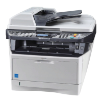
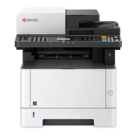
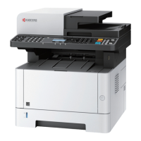
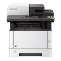
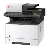
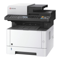
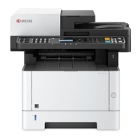
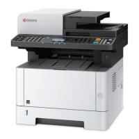
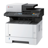
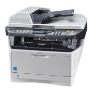
Identifies and illustrates the main external components of the machine.
Details the function and layout of the machine's operation panel.
Lists and illustrates optional accessories for the machine.
Lists all items included in the product packaging for unpacking.
Provides steps for removing shipping tapes from the machine.
Lists available maintenance modes with their item numbers and initial settings.
Describes the purpose and method for specific maintenance mode items.
Explains the format and components of error codes, including general and detailed classifications.
Lists general classifications of error codes with their descriptions.
Details error codes related to interrupted phase B in communication.
Lists error codes for unit-specific problems.
Lists error codes for G3 transmission issues.
Lists error codes for G3 reception issues.
Details error codes for V.34 transmission problems.
Details error codes for V.34 reception problems.
Explains the procedure for removing and installing the machine's left and right outer covers.
Describes how to remove and install the paper feed roller and pickup roller assembly.
Details the steps for removing and installing the retard roller assembly.
Explains how to detach and refit the MP paper feed roller.
Provides important notes for reassembling registration rollers, including spring replacement.
Outlines the procedure for removing and installing the document processor (DP).
Details the process of removing and installing the scanner unit.
Explains how to detach and refit the laser scanner unit (LSU).
Guides on how to replace the image scanner unit (ISU).
Describes the procedure for removing and installing the developer unit.
Details the process for removing and installing the drum unit.
Explains how to detach and refit the main charger unit.
Guides on removing and installing the transfer roller.
Outlines the procedure for removing and installing the fuser unit.
Describes the process of removing and installing the control PWB.
Explains how to detach and refit the power source PWB.
Guides on removing and installing the high voltage PWB.
Details the process of removing and installing the scanner PWB.
Explains how to detach and refit the FAX control PWB.
Describes the procedure for removing and installing the main motor.
Outlines removing and installing the DP rear and front covers.
Guides on removing and installing the DP drive PWB.
Explains how to clean or replace feed and forwarding pulleys.
Guides on cleaning or replacing the separation pad assembly.
Describes the cassette paper feeding mechanism.
Details the MP tray paper feeding mechanism.
Describes the paper conveying path within the machine.
Explains the structure and handling precautions for the drum unit.
Details the function and maintenance of the main charger unit.
Provides an overview of the scanner unit components.
Explains the operation and components of the image scanner unit (ISU).
Details the laser scanner unit (LSU) and its operation.
Describes the original feed mechanism within the document processor.
Explains how originals are conveyed within the document processor.
Details the switchback and eject mechanisms for originals.
Identifies and lists the various PWBs used in the machine's electrical system.
Locates and describes the function of switches and sensors in the machine.
Identifies other electrical components within the machine.
Lists electrical components specific to the document processor.
Provides wiring diagrams for the machine's electrical system.
Lists the circumference of recurring defects related to machine parts.
Lists recommended maintenance kits and their part numbers.
Details commands for configuring printer environment parameters via firmware.
| Brand | Kyocera |
|---|---|
| Model | ECOSYS M2030dn/PN |
| Category | All in One Printer |
| Language | English |