EasyManuals Logo

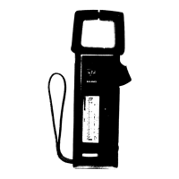
KYORITSU New SNAP 7 User Manual

KYORITSU New SNAP 7
12 pages
To Next Page IconTo Next Page
To Previous Page IconTo Previous Page
Page #7 background imageLoading...
Page #7 background image
As described
on
page
3, make
sure that the
voltage
test
leads and ohmprobe
arc
removed from
the instrument
during
the current
measurements.
If the ohmprobe
is lell
plugged
in, the
accuracy of
the current
measurement
may be affected
anrl
in addition
the fuse
located
in the ohmprobe
may be burned out
so that
the
reslstance
measurement
may not
be made,
SNAP AROL)ND
ONll
CONDUCTOR
ONI.Y
(I:ig.
ll). TII[, I\tE'ftjR
WILL
NOT
DIT,FLE('T
IF TWO
CONDUCTORS
ARE
I.NCLOSID WtTI{tN'I}iE.!AWS
(Fig.
12).
DURING
CURRENT MEASUREMENTS "REPLACE
BAT]'L]RY''
LAMP
ON THI:
SCALE PLA'tl1
LIGHTS tlP
INDICATING
THAT
THE BATTIiRY
IS WEAK.
Battery replacement
may be made
easily
by removing
the two
screws on the
battcry
compartment
cover
(Fig.
1)
as illustrated
on
page
3.
Immediately
after
completing
current
measurements, place
the lunction
selector
switch in the
"BATT.OFF"
position.
THE
FUNCTION
SELECTOR
SWITCH
SHOUI-D
ALSO
BE
LEI.'T ON THIS
POSITION
WHEN
THE
INSTRUMENT
IS
NOT
lN USI:.
F
ig.-
12
(6)

Questions and Answers:

Question and Answer IconNeed help?

Do you have a question about the KYORITSU New SNAP 7 and is the answer not in the manual?

KYORITSU New SNAP 7 Specifications

General IconGeneral
BrandKYORITSU
ModelNew SNAP 7
CategoryMultimeter
LanguageEnglish

Related product manuals