476
10
࿑ߩࠃ߁ߦߥࠆࠃ߁ߦ˴˴ߩߨߓߎߺ㊂ࠍ⺞ᢛߔࠆޕ
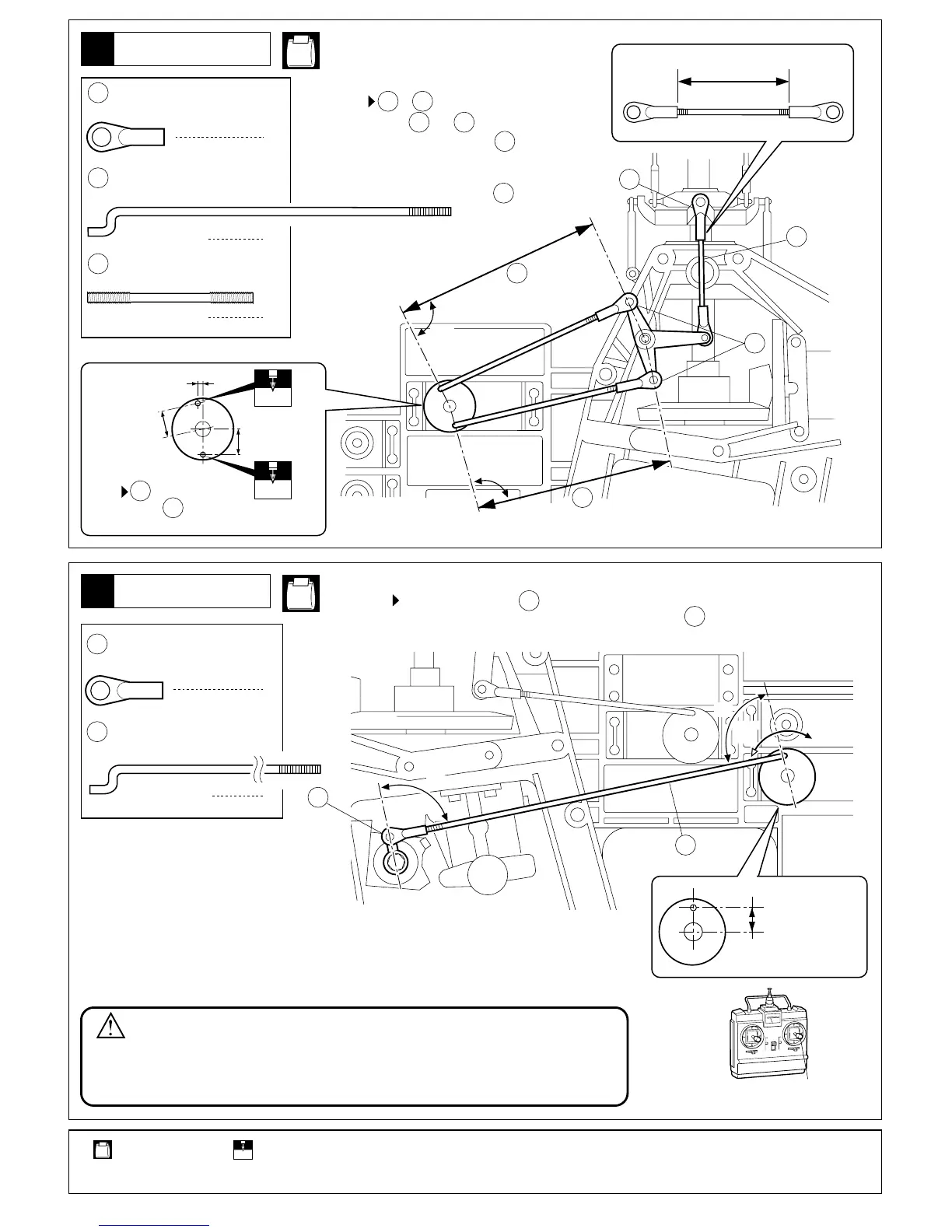
Refer to the diagram above and adjust the tightness of˴˴.
10
10
⚂12㨪14mm
approx. 12~14mm
ࠑ
ࠑ
ࠬࡠ
Slow
ࡂࠗ
High
10
10
477
A
B
⚂ࠑ
⚂ࠑ
˴˴㧩˴˴ߦߔࠆޕ
Make˴˴ and˴˴ of same length.
࿑ߩࠃ߁ߦߥࠆࠃ߁ߦ˴˴ߩ
ߨߓߎߺ㊂ࠍ⺞ᢛߔࠆޕ
Refer to the diagram above and
adjust the tightness of˴˴.
A B
A B
10
10
˴˴ߩขࠅઃߌ⟎
Screw˴˴down to the
spots indicated.
477
477
⚂2mm
approx. 2mm
⚂10mm
approx. 10mm
⚂10mm
approx. 10mm
1.7mm
1.7mm
⚂27mm
approx. 27mm
31
↪ߔࠆⴼޕ
Part bags used.
30
1
1
4.8mm ࡏ࡞ࠛࡦ࠼
Ball End
2160mm ࠕࠫࡖࠬ࠲ࡠ࠶࠼
˴˴˴˴ ˴Adjuster Rod
476
10
2
1
4.8mm ࡏ࡞ࠛࡦ࠼
Ball End
281mm ࠕࠫࡖࠬ࠲ࡠ࠶࠼
˴˴˴˴ Adjuster Rod
477
10
VR-8
ࠛ࡞ࡠࡦࡦࠤࠫ
Aileron Linkage
VR-8
ࠬࡠ࠶࠻࡞ࡦࠤࠫ
Throttle Linkage
⼊๔
٨
WARNING :
1
240mm ࠕࠫࡖࠬ࠲ࡉ࡞ࡠ࠶࠼
˴˴˴˴ Adjustable Rod
430
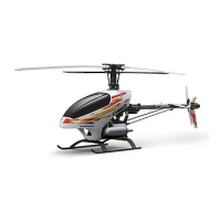
ࠨࡏߩേᣇะߦᵈᗧߔࠆޕㅒߦߥߞߡࠆߣޔࠛࡦࠫࡦ߇ᆎേߒߚᤨߦޔ
ࡔࠗࡦࡠ࠲߇㜞࿁ォߢ࿁ࠅޔ߿⎕៊ߩේ࿃ߦߥࠅ߹ߔޕ
Ensure the throttle servo moves into the correct direction! If it moves into the
opposite direction, the main rotor will rotate at high rpm when starting the engine.
This is dangerous as it may result in damages and, worse, serious accidents!
ᄩ
Neutral
2mmߩⓣࠍߌࠆ㧔㧕ޕ
2mm
Drill holes with the specified diameter (here: 2mm).
18
 Loading...