Do you have a question about the KYOWA DPM-900 Series and is the answer not in the manual?
Lists all included accessories with quantities.
Covers essential safety warnings, guidelines, and symbols used in the manual.
Explains specific words, symbols, and examples for clarity.
Provides an overview of the DPM-900/950 series features and benefits.
Details the general system setup for measurement using the DPM-900/950 series.
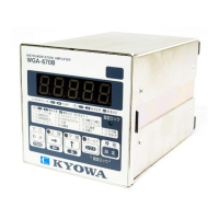
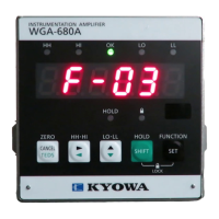
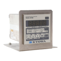
Describes the function of each button, switch, and indicator on the front panel.
Details the purpose of each connector and switch on the rear panel.
Guides on connecting input and output devices for measurement.
Instructions for connecting AC or DC power supply to the unit.
Outlines the initial configuration steps and switch settings.
Explains how to connect strain gages and transducers to the input connector.
Details how to connect external instruments to the output terminals.
Provides step-by-step instructions for safely turning the device on and off.
Describes how to choose between Normal, TEDS, and ACTL LOAD modes.
Explains the electronic balancing process for accurate measurements.
Guides on setting the internal gain for accurate strain measurement.
Explains how to configure the low-pass filter for signal conditioning.
Details how to enable or disable the high-pass filter for DC component removal.
Guides on fine-tuning the zero point of the output signals.
Explains how to fine-tune the device's sensitivity.
Describes the input capabilities and supported sensors for strain measurement.
Explains the characteristics of the two independent output systems.
Details the necessary preheating time for stable measurement.
Explains how to check for wire breaks in the input system.
Covers balancing range and the balancing procedure.
Describes the function to remove the zero point of output signals.
Details methods for setting internal gain using CAL, TEDS, or ACTL LOAD.
Explains the LPF characteristics and its roles in signal processing.
Details how to use the calibration signal for strain measurement.
Describes how to use the key-lock feature to prevent parameter changes.
Explains how to synchronize multiple units for simultaneous measurement.
Details the use of the centralized connector for power and signals.
Lists functions that can be controlled remotely.
Details the functions and models of bridge boxes for strain gage configurations.
Describes the rubber stand used for fixing a single unit.
Lists available extension cables for remote measurements.
Explains how the filter reduces external high-frequency noise.
Details the models and features of carrying cases for multichannel measurements.
Lists functions like batch balance, calibration, and OSC sync for carrying cases.
Instructions for carrier synchronization between multiple carrying cases.
Remedies for issues where the unit does not power on, including fuse checks.
Troubleshooting steps when balancing fails, checking the bridge and sensors.
Solutions for when the monitor shows no output or input issues.
Addresses issues with unstable zero points, checking preheating and compensation.
Troubleshooting steps for excessive noise from interference or electric potential.
Details various error codes and their corresponding solutions.
Comprehensive list of electrical and performance specifications for different models.
Details signal-to-noise ratio and output voltage specifications.
Illustrates the internal circuitry and explains the signal processing principles.
Provides physical dimensions and mounting information for the unit.
Table relating wire-breaking locations to specific error codes.
Graphs showing amplitude and phase response of the LPF.
Graphs illustrating frequency response for different models.
Methods and formulas for calculating strain and stress from waveforms.
Explains corrections needed based on the number of strain gages used.
Provides correction factors for measurements using extension cables.
Comprehensive table of error codes, status, and remedies.
Details the connection and grounding for the E terminal.
Provides definitions for key terms and acronyms used in the manual.