Do you have a question about the KYOWA WGA-120A and is the answer not in the manual?
Essential pre-use safety guidelines and manual handling instructions for safe operation.
Instructions for safe power supply connection and voltage requirements.
Guidelines for preventing operational issues caused by electrical noise and interference.
Warnings against placing equipment near welding machines to prevent data errors and malfunctions.
Discusses potential failures and performance degradation of electrolytic capacitors.
Details how EEPROM issues can lead to malfunctions or degraded performance.
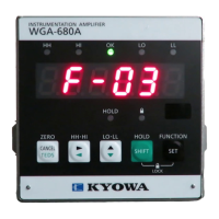
Explains the function and color indication of the pilot lamp.
Describes the function of the coarse adjustment for the zero output signal.
Details the fine adjustment for the zero output signal.
Explains the function of the sensitivity (SPAN) adjustment.
Describes the operation of the BAL/CAL switch for auto balance adjustment.
Identifies the terminal for connecting strain gage transducers.
Specifies the terminals for proportional output signal (voltage/current).
Identifies terminals for synchronous operation of multiple units.
Terminal for controlling auto balance adjustment via external contact.
Terminal for connecting the power supply.
Terminal for connecting the protective ground.
Details the default factory settings for bridge excitation, output, sensitivity, CAL, and frequency.
Guidance on setting bridge excitation voltage based on transducer requirements.
Instructions for setting sensitivity based on transducer rated output.
Information on setting the calibration value (CAL) using tables or formulas.
Guidance on setting the frequency response for desired measurements.
Step-by-step procedure for changing jumpers on the manual balance model.
Step-by-step procedure for changing jumpers on the auto balance model.
A practical example demonstrating how to configure jumpers for specific settings.
Instructions for mounting the WGA-120A unit onto a panel or DIN rail.
Detailed steps for connecting the power supply to the unit.
Guidelines for connecting strain gage transducers to the unit.
Procedures for connecting multiple transducers in parallel.
Instructions for using strain gages, including synchronous operation.
How to connect the auto balance control input terminal for auto balance function.
Information on connecting the analog voltage or current output terminals.
Steps for powering on the WGA-120A unit and initial warm-up.
Procedures for adjusting the zero balance for both auto and manual models.
Methods for adjusting the span using actual load calibration or CAL.
How to correct measurement errors introduced by using extension cables.
Step-by-step guide to perform the auto balance adjustment.
Comprehensive technical specifications of the WGA-120A.
A visual representation of the internal circuitry and signal flow.
Physical dimensions and panel cut-out details for installation.