MTD 112 30 06/97
6.2 CONNECTORS & CABLES
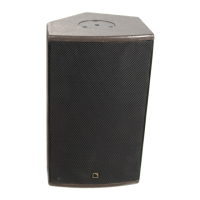
a) MTD 112 :The connectors at both ends of the 2 conductors cables for connecting the
MTD 112 are of the 4 pins Speakon type.
Two Speakon sockets are provided on the front panel of the MTD 112 LLCa controller, one
per channel.
The wiring is as follows:
1+ = +
1 - = -
2+ = NO CONNECTION
2 - = NO CONNECTION
b) In order to preserve a correct damping factor, which is essential both for the sonic
qualities of the system and to prevent overshoot of the cone displacement function (which
can eventually result into mechanical damage), it is desirable to keep the loudspeaker wires
as short as possible, and of a gauge offering a low resistance per unit length.
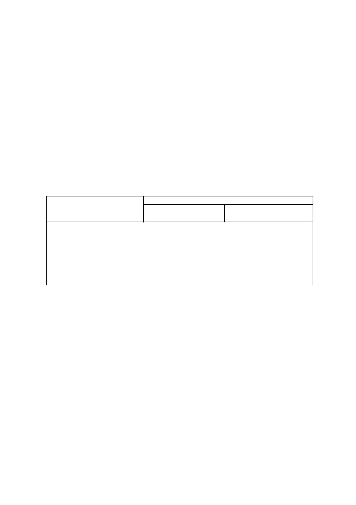
The following chart provides the information on the minimum wire section vs. length.
Section area / Gauge Max.recommanded length
8Ω 4Ω
Metric(mm2) Imperial Metric Imperial Metric Imperial
2.5 13 10 m. 30 ft. 5 m. 15 ft.
4 11 18 m. 60 ft. 9 m. 30 ft.
6 8 30 m. 100 ft. 15 m. 50 ft.
10 6 45 m. 150 ft. 23 m. 75 ft.
c) MTD 112 LLCa Line -level connections
All the line-level connectors are of the 3 pins XLR type. The wires are microphone type, i.e.
one pair of conductors plus a conducting shield.
The wiring is as follows:
BALANCED
1 = Earth
2 = Hot
3 = Cold
On the MTD 112 LLCa, the inputs and the outputs are balanced.
 Loading...