MTD 112 36 06/97
c) turn the whole system ON
d) switch the generator ON, with level at minimum.
e) crank up the level until you obtain a reasonably measurable sound ("Plop,Plop")
2 Receiver
a) connect a microphone to the input of the generator
b) switch the "HOT PIN" to 2 or 3 according to the wiring of the microphone
c) switch to EXT.MIC
d) switch the PC 80 receiver ON
e) Place the microphone near each loudspeaker fed with the signal of this output of the
mixing desk, and observe if the lightened LED is the red one (negative polarity) or the green
one (positive polarity)
3 Loudspeakers
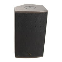
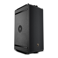
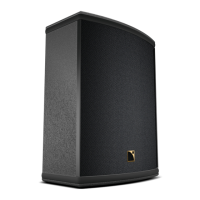
a) MTD 112 enclosure : Place the microphone near the center of the loudspeaker, at the
distance comprised between 5 cm and 50 cm. The green LED must be lightened at every
« Plop », showing that the polarity is positive.
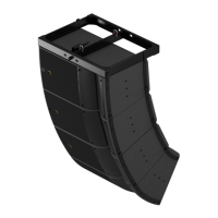
b) SUBS: All the subs must show a negative polarity, with the red LED on. Be careful with
the MTD 118! because of its double chamber load, this polarity check provides opposite
results according to the location of the microphone. The microphone should be located very
near of the exit slot, and at the center of it. Placing the microphone at one end of the exit
slot will provide inverse results. When the location of the microphone is in center, the
polarity must be positive polarity (green LED).
4 Do it again, for each output of the mixing desk.
7.1 MTD 112 ENCLOSURE
a) Periodic check.
The response of the enclosure should be checked periodically, to prevent deviations due to
wear, shocks or any event. This should be done at least every two years for systems not
being submitted to heavy-duty use. For systems being used nearly everyday, or systems
touring, this period should be reduced to six months.
This check can be performed with a well displayed 1/3 octave analyzer, or even preferably a
TEF or a MLSSA analyzer. It should refer to the on axis amplitude/frequency response
presented in page 18 of the present document.
The fixing of the chassis driver assembly should also be checked, as the metal screws
could become loose after being submitted to intense, long duration mechanical vibrations.
The quality of the contacts and the locking of the SPEAKON connector should also be
checked.
b) Phase check.
Whenever a diaphragm is replaced, the wiring polarity should be checked with a phase
check device as mentioned in 6.5 (page 35).
7. MAINTAINANCE & MISCELLANEOUS
 Loading...