Do you have a question about the Laars MASCOT LX and is the answer not in the manual?
Provides an overview of the manual's purpose and scope.
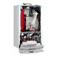
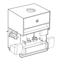
Details how to access internal components by removing panels.
Describes the location and content of the appliance's rating plate.
Explains the system of letters and numbers identifying the appliance's characteristics.
Guidelines for selecting a suitable location for installation.
Specifies required clearances for vent terminals to ensure safe operation.
Explains how the unit obtains combustion air, either from the space or via ducting.
Details requirements for spaces communicating with the outdoors for combustion air.
Covers requirements and considerations for the exhaust venting system.
Diagram showing how to open the Mascot LX panels for access.
Specifies requirements for choosing a suitable wall and clearance for the appliance.
Details clearances for vent and combustion air terminals.
Explains requirements for combustion and ventilation air.
Details methods for providing combustion air from the installation space.
Covers requirements and considerations for the exhaust venting system.
Guidelines for locating the side wall vent terminal.
Details requirements for gas piping installation, sizing, and safety.
Information on the pump's capacity and recommended piping configurations.
Guidelines for piping the central heating system.
Details how to connect the main power supply to the unit.
Information on connecting the boiler and system pumps.
Explains the 24Vac transformer and its circuit breaker.
How to connect the call for heat signal.
Connecting the outdoor sensor for weather-dependent control.
Connecting controls for indirect water heaters or DHW sensors.
Connecting the system sensor for boiler operation.
Connecting external 0-10VDC signals for modulation or setpoint.
Describes the digital display as the main interface for monitoring and adjusting parameters.
Initiating a call for heat and the ignition sequence.
How outdoor temperature influences heating setpoints.
Integrating with building management systems via 0-10VDC input.
DHW demand triggered by a flow sensor in Combi models.
DHW demand initiated by an aquastat in an indirect water heater.
DHW demand initiated by an optional DHW sensor.
Procedures for manually configuring boilers in a cascade system.
Step-by-step guide for filling and purging the boiler and system with water.
Procedures for checking installation and starting the burner.
Essential checks before operating the burner.
Describes the step-by-step process of the unit's operation.
Discusses causes and symptoms of short cycling.
Provides diagrams and part numbers for replacement components.
| Category | Boiler |
|---|---|
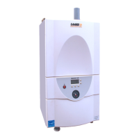
| Brand | Laars |
| Model | MASCOT LX |
| Fuel Type | Natural Gas or Propane |
| Boiler Type | Condensing |
| Efficiency | Up to 95% |
| Vent Type | Direct Vent |
| Water Connections | 1" NPT |
| Heat Exchanger Material | Stainless Steel |
| Vent Diameter | 2" or 3" |
| Weight | 150 lbs |