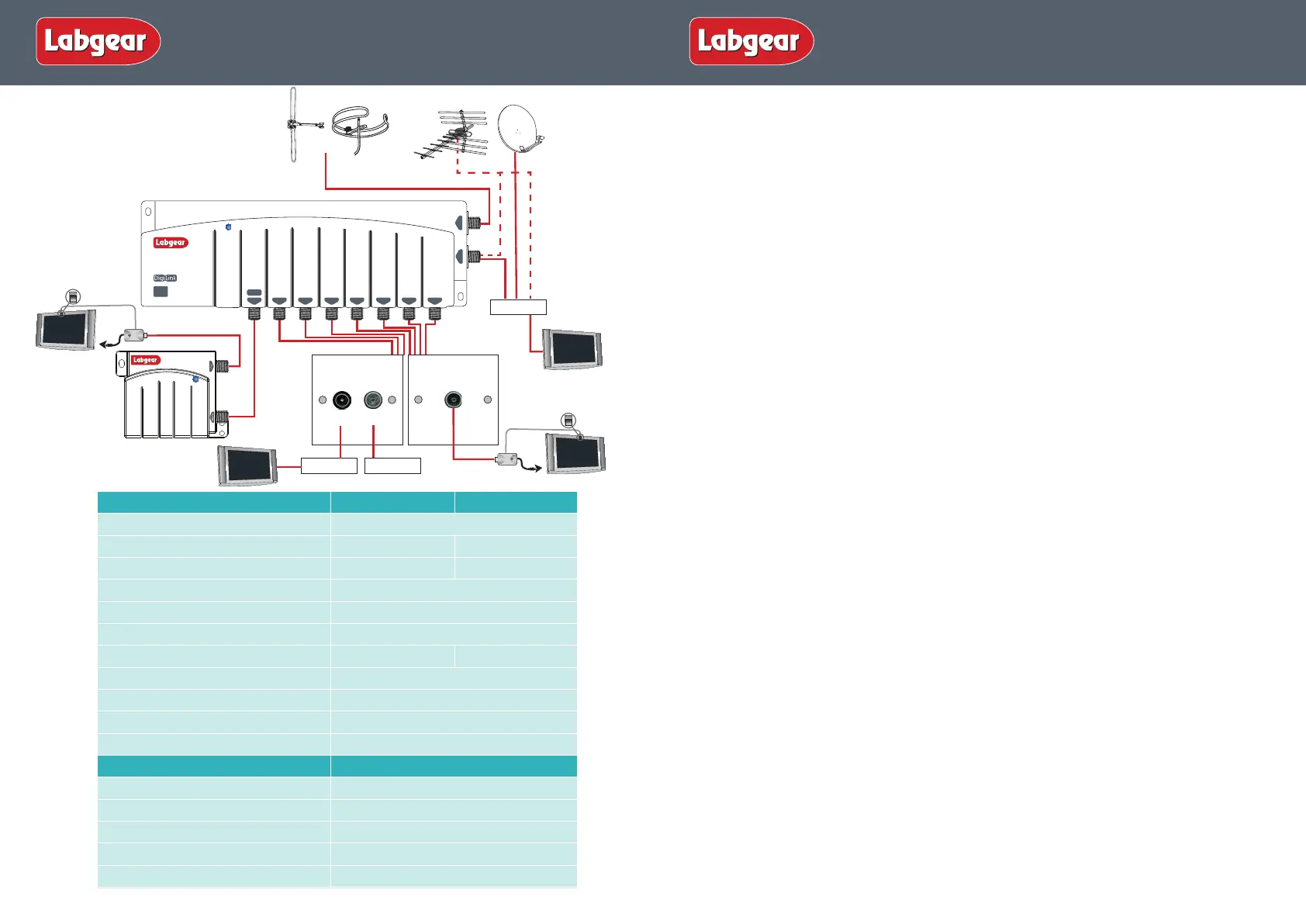
Remote Rooms
Or
VCR/DVR
Digi Eye
MRX955
TV
RF In
Digi Eye
MRX955
SAT
RF2 OUT
1
VHF
2 3 4 5 6
UHF
7 8
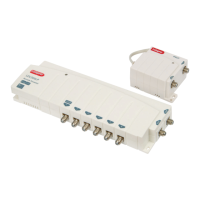
LDL208LP
Remote Powered
POWER
Lte
800
READY
PSM114E
TV
FM/DAB
PSW122
Suitable for combined
TV and Radio outlet
PSW111
Suitable for TV outlet
RF In
TV
TUNER
TV
TV
Installation
Important note: attention is drawn to the General Safety Precautions Panel on page 4 which
contains advice on safe installation and operation of these products.
Location
Choose a location for the amplier from which it is convenient to run cables from the
antennas and to the system outlets. Typical examples of suitable locations are a loft space or a
cupboard. In weak signal areas it is best to keep the antenna cables as short as possible.
Select a cool, dry location to install the amplier. This means a location where the ambient
temperature will remain between -10°C and +40°C, and which is free from risk of dripping or
splashing water.
The xing location should allow adequate access to the equipment for wiring and maintenance.
Clearance of at least 25mm should be allowed around the top and left hand side of the amplier
and also around the three sides of the power supply that don’t have connections to allow
adequate ventilation. More clearance will be needed on the sides with connections to allow
access for cables.
Fixing
The amplier should be xed to a wall or other suitable hard surface, using suitable screws and
masonry plugs (not supplied). The amplier should not be left supported by its own wiring, nor
should it be left resting on a carpet or other insulating and/or inammable surfaces.
Electricity Supply
Fixed wiring and connection of the electrical supply to these products should be carried out in
accordance with BS7671 (IEE Wiring Regulations) .
Each amplier is supplied with a separate PSUF tted with a 13A mains plug. If this is not
suitable, see General Safety Precautions Panel on page 4. As an alternative to the use of plug
and socket connection, the power supply may be connected to the mains using a switched
fused connection unit BS 1363-4. A 3 Amp fuse to BS1362 should be tted in the fused
connection unit. If the power unit is connected to the supply other than by means of its tted
fused plug or a fused connection unit, It must be protected by a non-time delayed fuse or a
type B MCB at the distribution board of rating not exceeding 6A. An isolating switch should be
provided near to the unit to allow it to be disconnected from the supply when necessary.
Signal Connections
Input and output signal connections are made using F type (IEC 60169-24) connectors.
Good quality plugs should be used, preferably of the crimp on type. If twist on connectors are
used make sure they are the right size to t the cable you are using. For outside connections
use waterproof connectors. Attention is drawn to the need to maintain DC continuity through-
out the system for correct operation of infra-red remote control functions
Resetting RF Channel on a Digibox
1. Switch on your Sky™/Sky+™/ Sky+ HD™ receiver and view on your main television.
2. Press the SERVICES button on your Sky™ remote.
3.
Select SYSTEM SETUP option (for SKY+ HD there is no SYSTEM SETUP option press 0 instead).
4. Press the following buttons in sequence: 0, 1, SELECT (for SKY+ HD this is a hidden option
and does not appear on screen). You should now see the installers’ menu.
5. Select the RF CHANNEL NUMBER option and key in a new channnel number from 21-58.
Make a note of the channel number you choose as you may need it when tuning your
other TVs.
3
2
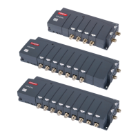
Amplier
LDL206LP LDL208LP
No of Inputs
2
No of Outputs
6 8
Return Path Frequency Range
5-15MHz 5-15MHz
Return Path Gain
-4dB
Frequency Range
UHF: 470-790MHz FM/DAB: 47-300MHz
UHF/FM/DAB Gain per port
8dB
Max Out put level (IMA3-60dB). EN50083-5
98dBµv 96dBµv
Noise Figure
3.5dB
All Ports IR Enabled
9V 15mA short circuit protected
Isolation between outlets
20dB
Dimensions
265 x 95 x 35mm
Power Supply
PSUF
DC Output
12VDC at 200mA max.
Output Voltage Tolerance
± 5%
Power Requirement
220-240V~50Hz at <3W
Signal Insertion Loss
0.5dB
Dimensions
88 x 67 x 45mm
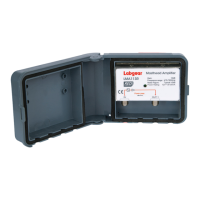
Installation Instructions
Please Note: A UHF aerial can be
connected directly to the UHF input
on the amplier or connected via
a Satellite Receiver.
Installation Instructions
 Loading...