that provides a gain greater than 2.06. The +V supply for the op-amp would have to be greater than 10 volts.
For bipolar output ranges, such as ±10 volts, a similar op-amp circuit can be used to provide gain and offset, but of course the op-
amp must be powered with supplies greater than the desired output range (depending on the ability of the op-amp to drive it’s
outputs close to the power rails). For example, the EB37 experiment board provides power supplies that are typically ±9.5 volts. If
these supplies are used to power the LT1490A op-amp (linear.com), which has rail-to-rail capabilities, the outputs could be driven
very close to ±9.5 volts. If ±12 or ±15 volt supplies are available, then the op-amp might not need rail-to-rail capabilities to achieve
the desired output range.
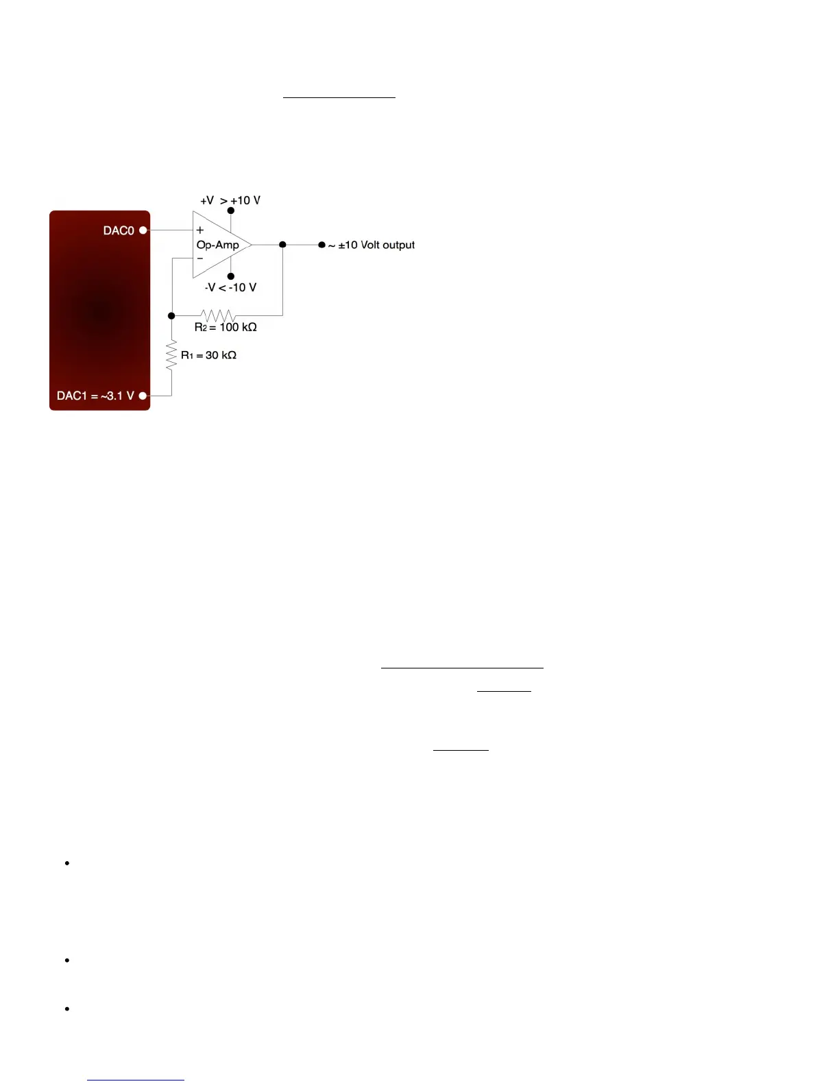
A reference voltage is also required to provide the offset. In the following circuit, DAC1 is used to provide a reference voltage. The
actual value of DAC1 can be adjusted such that the circuit output is 0 volts at the DAC0 mid-scale voltage, and the value of R1 can
be adjusted to get the desired gain. A fixed reference (such as 2.5 volts) could also be used instead of DAC1.
Figure 2-8. ±10 Volt DAC Output Circuit
A two-point calibration should be done to determine the exact input/output relationship of this circuit. Refer to application note
SLOA097 from ti.com for further information about gain and offset design with op-amps.
2.9 - Digital I/O
The LabJack UE9 has 23 digital I/O. The LabJackUD driver uses the following bit numbers to specify all the digital lines:
0-7 FIO0-FIO7
8-15 EIO0-EIO7
16-19 CIO0-CIO3
20-22 MIO0-MIO2
The UE9 has 8 FIO (flexible digital I/O). The first 4 lines, FIO0-FIO3, appear both on the screw terminals and on the DB37
connector. These connections are electrically the same, and the user must exercise caution only to use one connection or the
other, and not create a short circuit. The upper 4 lines appear only on the DB37 connector. By default, the FIO lines are digital I/O,
but they can also be configured as up to 6 timers and 2 counters (see Timers/Counters Section of this User’s Guide).
The 8 EIO and 4 CIO lines appear only on the DB15 connector. See the DB15 Section of this User’s Guide for more information.
MIO are standard digital I/O that also have a special multiplexer control function described in Section 2.7 above (AIN). The MIO are
addressed as digital I/O bits 20-22 by the Windows driver. The MIO hardware (electrical specifications) is the same as the
EIO/CIO hardware.
All the digital I/O include an internal series resistor that provides overvoltage/short-circuit protection. These series resistors also
limit the ability of these lines to sink or source current. Refer to the specifications in Appendix A.
All digital I/O on the UE9 have 3 possible states: input, output-high, or output-low. Each bit of I/O can be configured individually.
When configured as an input, a bit has a ~100 kΩ pull-up resistor to 3.3 volts (all digital I/O are 5 volt tolerant). When configured as
output-high, a bit is connected to the internal 3.3 volt supply (through a series resistor). When configured as output-low, a bit is
connected to GND (through a series resistor).
The fact that the digital I/O are specified as 5-volt tolerant means that 5 volts can be connected to a digital input without problems
(see the actual limits in the specifications in Appendix A). If 5 volts is needed from a digital output, consider the following solutions:
In some cases, an open-collector style output can be used to get a 5V signal. To get a low set the line to output-low, and to
get a high set the line to input. When the line is set to input, the voltage on the line is determined by a pull-up resistor. The
UE9 has an internal ~100k resistor to 3.3V, but an external resistor can be added to a different voltage. Whether this will
work depends on how much current the load is going to draw and what the required logic thresholds are. Say for example a
10k resistor is added from EIO0 to VS. EIO0 has an internal 100k pull-up to 3.3 volts and a series output resistance of about
180 ohms. Assume the load draws just a few microamps or less and thus is negligible. When EIO0 is set to input, there will
be 100k to 3.3 volts in parallel with 10k to 5 volts, and thus the line will sit at about 4.85 volts. When the line is set to output-
low, there will be 180 ohms in series with the 10k, so the line will be pulled down to about 0.1 volts.
The surefire way to get 5 volts from a digital output is to add a simple logic buffer IC that is powered by 5 volts and
recognizes 3.3 volts as a high input. Consider the CD74ACT541E from TI (or the inverting CD74ACT540E). All that is
needed is a few wires to bring VS, GND, and the signal from the LabJack to the chip. This chip can level shift up to eight
0/3.3 volt signals to 0/5 volt signals and provides high output drive current (+/-24 mA).
Note that the 2 DAC channels on the U3 can be set to 5 volts, providing 2 output lines with such capability.
 Loading...