Appendix C - Enclosure and PCB Drawings
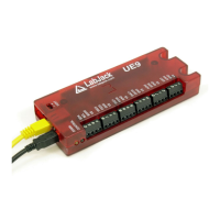
See below drawings of the UE9.
The square holes on the back of the enclosure are for DIN rail mounting adapters (TE Connectivity part #TKAD).
CAD drawings of the UE9 enclosure are attached to the bottom of this page. (DWG, DXF, IGES, STEP)
The UE9 enclosure base has a pair of slotted holes towards the communication end (left in below drawing), and another pair of
mounting holes at the opposite end (right in below drawing).