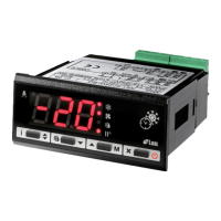
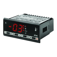
3. DISPLAYS
For approx. three seconds upon switching on, the instrument displays (internal self-test phase). Subsequent indications depend
on the operating status of the regulator. TABLE 2 gives the indications associated with the various states.
The temperature measured by the sensor is processed by the microprocessor to display it in the most representative way. For this
purpose it may be corrected with a fixed offset, assigning the parameter OS1 a value other than zero, and displayed in the desired
scale by setting the parameter SCL: with SCL=1°C the temperature is displayed in the Celsius scale with auto-range 0.1°/1°C;
with SCL=2°C or °F the temperature is displayed with a resolution of a degree in the Celsius or Fahrenheit scale respectively.
Prior to display, the temperature is processed by a special algorithm, which allows the simulation of a thermal mass directly
proportional to the SIM value; the resulting effect is a reduction in the oscillation of the displayed value.
The output status is shown through the luminous point on the display.
CAUTION: when changing the display scale SCL, the parameters related to the absolute (SPL, SPH, 1SP) and differential (1HY,
1PB, OS1) temperatures MUST be reconfigured.
TABLE 2
4. OPERATION DESCRIPTION
4.1. CONTROLLER STANDBY. Parameter BAU determine the functions associated with the button : with BAU=NON the button
is used to exit from the setup or to abort the autotuning routine; with BAU=SBY the button has an additional function, i.e. it can
also be used to switch on and off the controller: keeping this button pressed for about 3 seconds changes the controller status (on
/ stand-by). When it’s on standby, the controller shows OFF, the output is off and it’s not possible to have access to the parameter
setup.
4.2. T
YPE OF CONTROL. The output may operate in the ON/OFF or PID mode: 1Y=HY is fixed for ON/OFF control, 1Y=PID
for PID control.
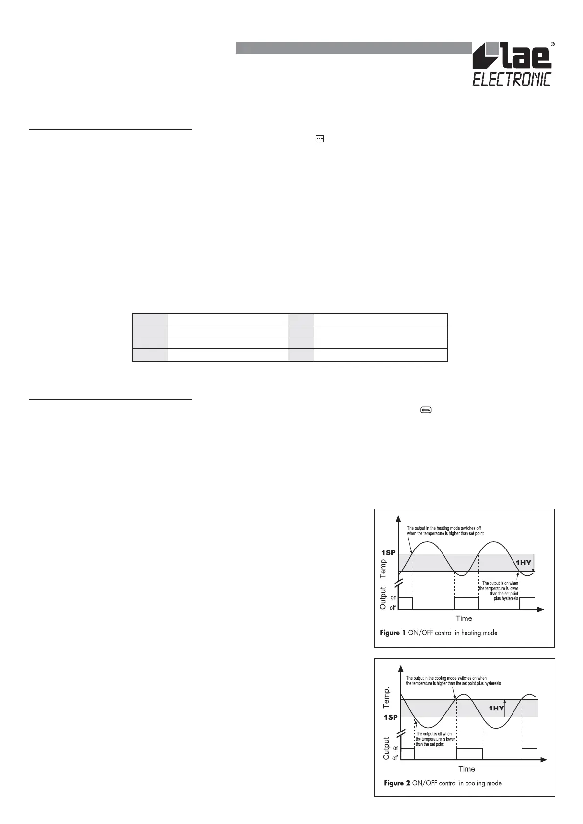
4.3. ON/OFF
CONTROL. In the ON/OFF mode the output is ON or OFF in
relation to the input temperature, set point (1SP) and hysteresis value (1HY). The
hysteresis indicates the amplitude of deviation of the temperature from the set point
in order to reactivate the output. Increasing the hysteresis value decreases the
switcheovers of the output, while decreasing the hysteresis value gives finer control.
For the output to operate in the heating mode, assign a negative value (see Figure
1) to 1HY; assign a positive value for control in the cooling mode (see Figure 2).
With 1HY=0 the output is permanently cut out. After a switchover the output
remains in the new state for a minimum time of 1CT seconds irrespective of the
temperature value.
4.4. PID
CONTROL. In the PID mode the output is ON for a fraction of the cycle
time 1CT. The cycle time characterises the dynamics of the system to be controlled
and influences the accuracy of the control: the higher the system speed of response
the shorter the cycle time to obtain greater temperature stability and less sensitivity
to variations in load. Assign a negative value to 1PB to make the output operate in
the heating mode (see Figure 3) and a positive value for control in the cooling mode.
With 1PB=0 the output is permanently cut out.
INSTRUCTIONS FOR INSTALLATION AND USE.
--- Internal self-test (3 seconds) E1 In tuning: timeout 1error
5.4 Sensor T1 temperature E2 In tuning: timeout 2 error
or Over range or breakage T1 E3 In tuning: over range error
Tun / 5.4 Instrument in auto-tuning OFF Controller standby