EasyManua.ls Logo

LAE electronic SMD34RU - User Manual

LAE electronic SMD34RU
5 pages
Print Icon
To Next Page IconTo Next Page
Loading...
We thank you for choosing an LAE controller. Before proceeding to the installation, please read this instructions sheet carefully; only in this way you will
obtain maximum performance and safety.
1. INSTALLATION
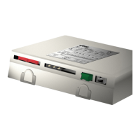
1.1 The SSD90 must be secured to the panel by means of screws or rivets to be inserted into the appropriate slots. Protection is IP30, therefore please
locate the unit in a position ensuring that no liquid infiltrates and damages the board.
1.2 Probes, power supply and outputs must be connected strictly according to the indications appearing on the board; the cables can pass through the
hole on the unit side. For supply voltage and maximum switchable loads, please read the label on the enclosure. The flat cable of the remote unit must
be connected making sure that the mechanical polarity is respected, finally secure the flat cable firmly by means of the suitable cable tie.
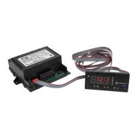
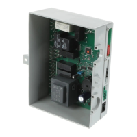
1.3 The SMD12RU remote unit is secured to the panel by means of the two springs at its box sides. The unit is mounted on the panel through a 29x71
mm opening, exert a moderate pressure so as to get the SMD12RU to adhere to the panel perfectly.
Differently, as to the SMD34RU model, remove the two side screws and open the enclosure. Mount the front of the remote unit through a 31x185 mm
opening on the panel and then match it to the rear cover. Then finally close the box by means of the screws.
1.4 Probe T1 measures the air temperature and is used for the thermostat function. It must be located inside the room in a place that well reflects the
temperature of the preserved product. Probe T2 measures the evaporator temperature and must be secured to it in the place where the maximum frost
growth occurs.
1.5 The unit works with an ambient temperature between –10°..+50°C and 15%..80% of relative humidity. To reduce the effects of electro-magnetic
interference, place the probe and signal cables as away as possible from power lines.
CAUTION: If the relays switch a large load frequently, we suggest you contact us to obtain information about the relay contact life.
Where delicate or valuable products have to be maintained under strict conditions, we suggest you use a second unit for limit and alarm purpose.
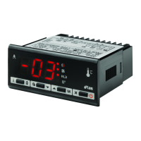
2. OPERATING LEVELS
For three seconds from the power-up the display illuminates a dash (self-check phase). The following indications depend on the operating status of the
controller and from the menu level activated by the operator.
On TABLE 1 you can find status, levels and relevant indications.
2.1 S
TANDBY
. Setting the parameter OFF to YES enables the button that allows to put the SSD90 on standby, that is excluding output control and
the buttons with the exception of the light command (manually or door controlled). With OFF=NO, the button is inhibited.
A permanent indication on display indicates that the outputs are off.
2.2 N
ORMAL
. During normal operation the display shows the room temperature or, if the controller is being performing defrost and the parameter DDY
is greater than 0, the indication . In this latter case, the indication will remain beyond defrost end for the time programmed with DDY.
2.3 A
LARM
. An anomaly is reported on display through the flashing of an abbreviation indicating its cause: / high/low alarm temperature in
the room; opened door; periodic condenser cleaning; / failure of probe T1/T2.
2.4 I
NFO MENU
. By pressing button you enter the information menu. In this menu it’s possible to start a manual defrost, display the instantaneous T1
E2
E1
CLN
DO
LO
HI
DEF
OFF
INSTRUCTIONS FOR INSTALLATION AND USE.
SSD90Bxx (x-C)
SMD12RU
SMD34RU
S
TANDBY
N
ORMAL
I
NFO MENU
I
NFO DATA
S
ETUP
P
ARAMETER
MENU VALUE
OFF -20 DF =DF= ADR 255
Not in Room
Manual defrost Waiting for Peripheral
operation
temperature
start sequence address
DEF T1 -19 - - - - - -
Defrost Air ….
temperature
=HI= T2 -23 - - - - - -
High temperature Evaporator ....
alarm temperature
- - - T3 SPH -18
.... .... Max.
Setpoint
=E1= PC 47 SPL -25
Probe T1 Access Min.
failure code Setpoint
TABLE 1
Question and Answer IconNeed help?

Do you have a question about the LAE electronic SMD34RU and is the answer not in the manual?

Overview

The LAE SSD90Bxx(x-C) is a series of electronic controllers designed for refrigeration systems, offering a range of functions for temperature control, defrost management, and alarm monitoring. The series includes models such as SSD90B35E-C and SSD90B55E-C, with variations in input/output configurations.

Function Description

The primary function of the SSD90 series is temperature control, based on the comparison between the temperature measured by probe T1, the setpoint (SP), and the hysteresis (HYS). The thermostat operation can be configured for cooling (HYS > 0) or heating (HYS < 0), or permanently excluded (HYS = 0). The controller also manages defrost cycles, which can be initiated automatically based on a built-in timer or manually. Evaporator fans are controlled in conjunction with the compressor, with options for proportional control or stopping when a door switch is activated. The device includes comprehensive alarm functions for various conditions, such as power failure, probe faults, open doors, and periodic condenser cleaning. It also supports light control, either manually or automatically via a door switch, and offers serial communication (RS485) for integration with supervisory software.

Important Technical Specifications

  • Temperature Range: Setpoint (SP) can be set between SPL and SPH, where SPL is -40° to SPH and SPH is SPL to +250°.
  • Hysteresis (HYS): Configurable from -30° to +30°.
  • Defrost Frequency (DFR): 0 to 24 (defrosts per 24 hours). DFR=0 disables timed defrost.
  • Defrost End Temperature (DLI): 0° to +70°.
  • Defrost Timeout (DTO): 1 to 120 minutes.
  • Defrost Type (DTY): OFF, ELE (electric), GAS (hot gas).
  • Drain Down Time (DRN): 0 to 30 minutes.
  • Defrost Display Control (DDY): 0 to 60 minutes.
  • Evaporator Fan Proportional Control (FPC): 0 to 5.
  • Fan Restart Temperature (FDD): -40° to +70°.
  • Alarm Differentials: Low alarm (ATL) -25° to 0°, High alarm (ATH) 0° to +25°.
  • Alarm Delays: Temperature alarm (ATD) 0 to 120 minutes, Door alarm (ADO) 0 to 120 minutes.
  • Condenser Alarm Temperature (ACT): 0° to 250°.
  • Compressor Safety Stop Delay (CSD): 0 to 30 minutes.
  • Condenser Fan Temperature (CFT): -40° to +250°.
  • Compressor Rest Time (CRT): 0 to 30 minutes.
  • Cooling Duty Cycle for T1 Fault (CDC): 0 to 10.
  • Display Scale (SCL): °C/°F.
  • Probe Offsets: OS1, OS2, OS3 (-15° to +15°).
  • Display Slowdown (SIM): 0 to 100.
  • Peripheral Address (ADR): 0 to 255.
  • Periodic Condenser Cleaning (ACC): 0 to 120 weeks.
  • Total Current: Max. total current 25A.
  • Relay Outputs: Typically 8(3)A, 12(4)A, 20(6)A, with some models (B50, B55) having defrost relay on voltage-free contacts.

Usage Features

  • Installation: The device is designed for panel mounting. Wiring diagrams are provided for models like SSD90B35E-C and SSD90B55E-C, detailing connections for power supply, probes (T1, T2), door switch, and various relays (compressor, fans, defrost, lights).
  • User Interface: The controller features a display and buttons for navigation and programming. Parameters can be accessed and modified through a setup menu, which is protected by a passcode (PC=47). Quick access to setpoint adjustment is available during normal operation.
  • Temperature Control: The thermostat function ensures precise temperature management. In case of probe T1 failure, the output is controlled via a fixed time established by CDC, maintaining operation within 10-minute cycles.
  • Defrost Management: Defrost cycles can be timed or manually initiated. The defrost duration is determined by DTO or by reaching DLI if the evaporator probe (T2) is active. A drain down phase (DRN) allows for complete ice melting before cooling restarts.
  • Fan Control: Evaporator fans can follow the compressor cycle with proportional control (FPC) or stop when the door is opened (DS=YES). Fans restart based on FDD after defrost or after a 3-minute timeout.
  • Alarm System: The controller provides comprehensive alarm monitoring, including visual (flashing display) and audible (buzzer) alerts. The buzzer can be silenced by pressing a button, but the alarm indication persists until the condition is resolved. Alarm thresholds and delays are configurable.
  • Light Control: Lights can be controlled manually or automatically via a door switch, provided DS and LDO parameters are set to YES.
  • Serial Communication: RS485 port allows the controller to communicate with a supervisory system, providing access to all temperatures, status, and control parameters. Each unit in the network is identified by its ADR parameter.

Maintenance Features

  • Periodic Condenser Cleaning: The controller can be configured to issue a warning for periodic condenser cleaning (ACC parameter). When the programmed compressor running time is reached, a "CIN" message is displayed. The timer can be reset after cleaning by following a specific button sequence.
  • Troubleshooting: The alarm system helps identify operational issues such as probe faults or door left open. The display indications and alarm behavior provide clues for troubleshooting.
  • Warranty: LAE electronic Srl provides a 1-year warranty against defects in workmanship and materials from the date of production. The warranty covers repair or replacement of defective products recognized by their technicians. Damages due to exceptional operating conditions, misapplication, or tampering void the warranty.

LAE electronic SMD34RU Specifications

General IconGeneral
BrandLAE electronic
ModelSMD34RU
CategoryController
LanguageEnglish

Related product manuals