button and at the same time or . The exit from the setup takes place automatically after 30 seconds of no button activation or immediately by pressing
button .
The setpoint SP can be displayed and set also during the normal operation status with and or buttons. The setting range however remains within the
limits established with SPL and SPH.
Table 2
4. DISPLAYS
The temperatures measured by probes T1 and T2 are treated by the microprocessor in such a way as to display them in the most meaningful way. To achieve
this, the temperatures can then be corrected by the respective offsets OS1 and OS2 and displayed in degrees Celsius or Fahrenheit, depending on the value
set to SCL.
Caution: if you change the readout scale you must then IMPERA
TIVELY re-configure the parameters relating to the absolute temperatures (SP, DLI, FDR …) and
to the differential temperatures (HYS, ATL, ATH …).
The air temperature, offset by OS1, before being displayed is treated by a special algorithm allowing the simulation of a thermal mass directly propotional to
the value set to SIM. The resulting effect is a hunting reduction on the displayed value.
By setting DDY to values greater than 0, during defrost, instead of the temperature, the display shows DEF, which will remain beyond defrost end for the number
of programmed minutes.
5. THERMOSTAT FUNCTION
5.1 Temperature control is based upon the comparison between temperature T1, the setpoint SP and the hysteresis HYS. The thermostat operation is
determined by the value set to HYS: if greater than 0 there will be COOLING control, if lower than 0 there will be HEATING control, if equal to 0, the thermostat
will be excluded and the corresponding output will be switched off permanently.
Example 1: HYS 02, SP -20; relay Off with T1 -20° and On with T1 -18°.
Example 2: HYS –04, SP 70; relay Off with T1 +70° and On with T1 +66°.
The actual relay on switching is however only possible if since the off switching the minimum rest time CRT has elapsed.
The relay status is signalled by the relevant dot on the display.
5.2 In consequence to failure of probe T1, the display shows ERR and the output is controlled with a fixed time established by CDC. This determines the output
running time within 10 minute cycles.
Example: CDC 06, 6 minutes On, 4 minutes Off.
6. DEFROST
6.1 Defrost automatically starts every time the built-in timer matches the time necessary to obtain the defrost frequency determined with DFR. For example,
with DFR=4 there will be a defrost every 6 hours. With DFR set to 0, the timed defrost function is excluded.
Defrost can be started manually from the Info menu in the following way: select DF, press button first then simultaneously.
The built-in timer is set to zero every time the unit is switched on (power supply or standby) and every time defrost is started.
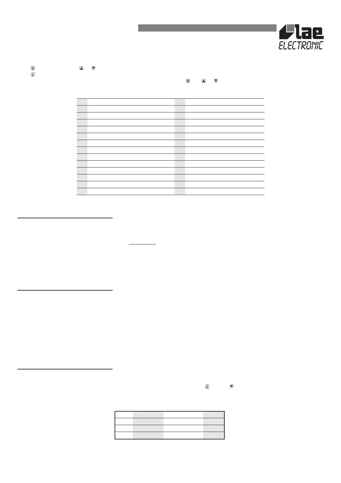
6.2 Once that defrost has been started, the outputs are controlled by the parameter DTY according to the following table:
6.3 Defrost terminates either when time DTO elapses or, if the evaporator probe is active (T2=YES), when temperature DLI is measured.
Now, if DRN is greater than 0, before cooling starts, all the outputs remain off for the time set to DRN. This phase, called drain down, will allow a complete
ice melting and the drain of the resulting water.
INSTRUCTIONS FOR INSTALLATION AND USE.
SPL -40.. SPH [°] minimum temp. set ATD 0.. 120 [min] temperature alarm delay
SPH SPL.. +250 [°] maximum temp. set ADD 0.. 120 [min] door alarm delay
SP SPL.. SPH [°] actual temperature set ACL 0.. 120 [weeks] condenser clean interval
HYS -30.. 0.. +30 [°] thermostat hysteresis CRT 0.. 30 [min] compressor rest time
DFR 0.. 24 defrost frequency/24h CDC 0.. 10 compressor duty cycle
DLI 0.. +70 [°] defrost end temperature OFF YES/NO standby key enable
DTO 1.. 120 [min] defrost timeout DS YES/NO door switch enable
DTY OFF/ELE/GAS defrost type LDC YES/NO door switched light
DRN 0.. 30 [min] drain down T2 YES/NO probe 2 enable
DDY 0.. 60 [min] defrost display control SCL °C/°F display scale
FRC 0.. 5 fan run control OS1 -15.. +15 [°] probe 1 offset
FDR -40.. +70 [°] fan re-start temperature OS2 -15.. +15 [°] probe 2 offset
ATL -25.. 0 [°] low alarm differential SIM 0.. 100 display slowdown
ATH 0.. +25 [°] high alarm differential ADR 0.. 255 address
DTY DEFROST COMPRESSOR FANS
OFF off off on
ELE on off off
GAS on on off
 Loading...