3
E1, E3, E5, E10, and E14 Series
Options
Flow Control
Models with an “F” in the 4th position of the model number are equipped with an output which functions as a ow
switch to conform with dry ve protection of UL1563. When the ow of the pump is equal to or greater than 26pm the
contacts will close and remain closed until the ow drops below 16pm. The contact will remain open until the ow is
26pm or greater, this is a low voltage isolated circuit, the contact is rated 5A at 250vac or 30vdc.
Variable Control
Models with a “V” in the 4th position of the model number are equipped with a dial that controls the pump speed.
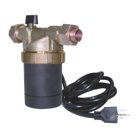
Temperature Control
Adjustable models with a “B” in the 4th position of the model number are equipped with a dial that controls the pump
to come on when the temperature drops below the set level. This can be adjusted between 68ºF (20ºC) to 158ºF
(70ºC).
Operation
1. Completely ll the system before operating the pump. Do not start the pump until the system has been lled. Make
sure the isolation valves are fully open and that there is water in the pump.
2. Purge air from the system prior to operating the pump. These two steps are very important. The pump should never
be allowed to run dry. This can severely damage the pump and will void the warranty.
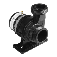
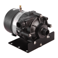
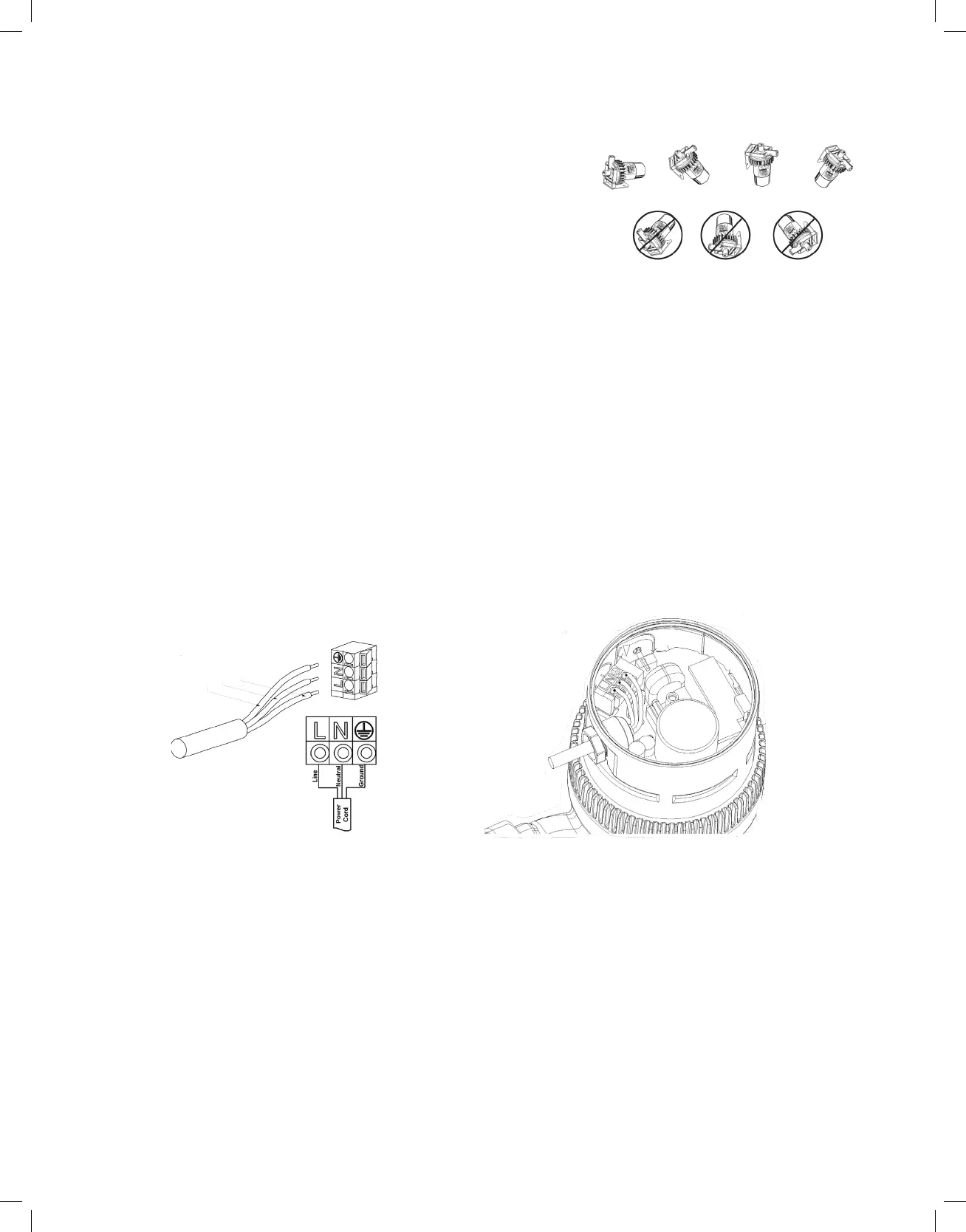
Mounting
For installation purposes the arrows on the side of the pump housing
indicate the direction of water ow through the pump. Check to make sure
the pump is adequately supported and that neither the pump or the piping
is severely stressed. Install the pump at a point closest to the highest static
pressure point, but above the absolute lowest point in the system to avoid
dirt and sediment build-up. If required by application and code, install a
safety relief valve to protect against over temperature and pressure. Do not
mount with the motor above the impeller. This can cause the pump to run dry
leading to premature failure of the pump which voids the warranty. Refer to
the gures below for proper orientation before installing the pump.
Correct Installation
Improper Installation -
Do NOT mount in these orientations
Electrical
These instructions must be followed to reduce risk of electrical shock. All work should be performed by a qualied
electrician and in accordance with the current national and local electrical codes and regulations. Consult the
nameplate for electrical data. The motor is impedance protected. Make certain that a properly sized circuit is
available. Wire size should be based on the current carrying (amp) capacity of the conductor. The pump must be
grounded in accordance with the current national and local codes. Ground wire should be copper with a current
capacity at least equal to that of the wire carrying power to the pump. Observe all minimum code requirements for
your jurisdiction. For pumps supplied with a power cord, the current carrying capacity of the cord is suitable for proper
operation. Make certain the receptacle is properly congured and in good working order. Check to make certain that
the circuit is properly sized for the load. Isolation valves are recommended for both sides of the pump. Valves should
be positioned to avoid leakage onto the motor and electrical compartment. All elbows, tees, and sharp bends in the
piping should be installed sufciently upstream or downstream of the suction and discharge ports. Avoid welding or
soldering close to the pump, which could cause damage to the unit. The pumps are exclusively for built-in use. After
installation, the end product must comply with the relevant product standard. Product standard regulations must be
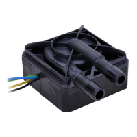
observed during tting and electric installation. For E5 95190 and E5 95191 types, where 2 cables are attached, both
cables for live (non SELF) voltage and are to be considered untouchable, as are all further connections and
connected parts. Installation and electric connections shall be carried out by professionals only.
E1, E3, and E5
E10 and E14
Green
White
Black
 Loading...