EasyManua.ls Logo

Laing E1 Series - User Manual

Laing E1 Series
6 pages
Print Icon
To Next Page IconTo Next Page
Loading...
E Series Model/ Nomenclature Matrix
E1, E3, E5, E10, or E14 - N C H R 1 W xx
Model 1st 2nd 3rd 4th 5th 6th 7th (Sufx position)
Family
Position Sufx Attribute
1st B Pump Housing is bronze or brass
N Pump Housing is Noryl, Luranyl, or Ultramid. Wetted metal parts are 316 Stainless
S Pump Housing is Stainless
T Pump Housing is Noryl, Luranyl, or Ultramid. Wetted metal parts are Titanium
H Pump Housing is Cast Iron
2nd C Center Discharge
S Side Discharge
3rd H Hose Connection
T Threaded Connection
S Sweat Connection
F Flanged Connection
4th V Variable Control
P PWM Control
A 1-5 volts Analog Control
C Temperature Control Fixed
R Temperature Control Adjustable
F Flow Control
N Fixed No Control
T Timer Control
S Self Regulates Pressure Control
5th 1 110-120 Volts AC
2 208-240 Volts AC
3 100-240 Volts AC
6th W With Cord
Blank No Cord
7th xx two digit sufx numbers changes with minor mechanical variations pump construction
Installation & Operating Manual
Please read this manual carefully before attempting to install, operate or maintain the product described. Failure to
comply with the information provided in this manual could result in personal injury and/or property damage. Retain this
manual for future reference.
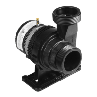
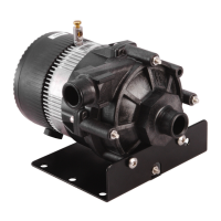
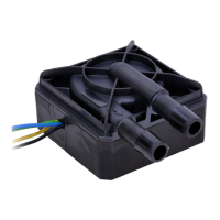
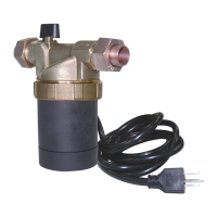
Description
Laing centrifugal pumps are designed for circulation and transfer of a variety of uids compatible with their
materials of construction limited to maximum uid temperatures and maximum line pressures as indicated below.
Unique leakproof integrated motor/pump design eliminates the need for conventional mechanical seals or other shaft
sealing devices. They are self lubricating and require no external lubrication.
E1, E3, E5, E10, and E14 Series

Questions and Answers

Summary

Introduction to Laing Pumps

Description

Overview of Laing centrifugal pump features and benefits, including leakproof design.

E Series Model; Nomenclature Matrix

Guide to understanding Laing pump model codes and their corresponding attributes.

Specifications and Unpacking

E Series Specifications

Detailed performance and operating parameters for E1, E3, E5, E10, and E14 series pumps.

Unpacking Instructions

Steps for checking the pump for damage or missing parts after delivery.

Safety and General Precautions

General Safety Information

Crucial safety advice, warnings, and precautions for handling and operating pumps.

U.L. Caution and Australia Note

Specific cautions regarding water-only testing and Australian installation standards.

Installation and Operation

Mounting

Guidance on correct and incorrect pump installation orientations and placement.

Electrical

Instructions for safe wiring, electrical codes, and power connections.

Options

Description of features like flow control, variable speed, and temperature control.

Operation

Steps for correctly starting, running, and purging air from the pump.

Maintenance and Troubleshooting

Maintenance

Procedures for pump upkeep, rotor replacement, and draining for freezing temperatures.

Trouble Shooting Chart

Solutions for common pump issues like motor not starting or no discharge.

Warranty and Company Information

Laing Warranty

Details of the product warranty terms, limitations, and return procedures.

Overview

The Laing centrifugal pumps, specifically the E1, E3, E5, E10, and E14 Series, are designed for the circulation and transfer of various fluids. These pumps feature a unique leakproof integrated motor/pump design, eliminating the need for conventional mechanical seals or other shaft sealing devices. They are self-lubricating and do not require external lubrication.

Function Description

These pumps are intended for fluid circulation and transfer within systems, provided the fluids are compatible with the pump's materials of construction. They are suitable for applications with specific maximum fluid temperatures and line pressures. The integrated motor/pump design ensures a leak-free operation.

Important Technical Specifications

The E Series models come in various configurations, indicated by a nomenclature matrix. Key attributes include:

  • Pump Housing Material:
    • Bronze or Brass (B)
    • Noryl, Luranyl, or Ultramid with 316 Stainless Steel wetted parts (N)
    • Stainless Steel (S)
    • Noryl, Luranyl, or Ultramid with Titanium wetted parts (T)
    • Cast Iron (H)
  • Discharge Type:
    • Center Discharge (C)
    • Side Discharge (S)
  • Connection Type:
    • Hose Connection (H)
    • Threaded Connection (T)
    • Sweat Connection (S)
    • Flanged Connection (F)
  • Control Type:
    • Variable Control (V)
    • PWM Control (P)
    • 1-5 volts Analog Control (A)
    • Temperature Control Fixed (C)
    • Temperature Control Adjustable (R)
    • Flow Control (F)
    • Fixed No Control (N)
    • Timer Control (T)
    • Self Regulates Pressure Control (S)
  • Voltage:
    • 110-120 Volts AC (1)
    • 208-240 Volts AC (2)
    • 100-240 Volts AC (3)
  • Cord:
    • With Cord (W)
    • No Cord (Blank)
  • Suffix: Two-digit suffix numbers indicate minor mechanical variations in pump construction.

Performance Specifications (Ranges across E Series models):

  • Min Fluid Temp: 10°C (50°F)
  • Max Fluid Temp: 55-95°C (131-203°F)
  • Max Pressure: 2-10.32 bar (29-150 PSI)
  • Max Ambient Temp: 50°C (122°F)
  • Min Storage Temp: -30°C (-22°F)
  • Voltage Range: 100-240V
  • Freq: 50-60Hz
  • Rated Wattage (max.): 12-110 W
  • Max RPMs: 2700-5340

Materials of Construction (wetted parts):

  • Pump Housing: Nylon/PPO (Plastic Housing Models), 316 Stainless Steel, Metal, Brass (Non-Plastic Housing Models)
  • "O" Ring: EPDM or Viton
  • Impeller: Nylon/PPO
  • Bearing: Carbon/Alumina Ceramic
  • All Other Wetted Parts: 316 Stainless Steel or Plastic

Usage Features

  • Installation: Pumps should be located as close to the fluid source as possible, with short and direct suction lines. They must be placed where the motor and electrical components are protected from weather and humidity. Piping should be supported independently of the pump. The pump housing has arrows indicating the direction of water flow. Proper orientation is crucial; do not mount with the motor above the impeller to prevent dry running.
  • Electrical: All electrical work must be performed by a qualified electrician in accordance with national and local codes. The motor is impedance protected. Pumps supplied with a power cord are suitable for proper operation with a correctly configured receptacle. Isolation valves are recommended on both sides of the pump.
  • Flow Control (Models with "F" in 4th position): Equipped with an output functioning as a flow switch for dry run protection (UL1563). Contacts close when flow is ≥26 gpm and open when flow drops below 16 gpm. This is a low voltage isolated circuit, rated 5A at 250vac or 30vdc.
  • Variable Control (Models with "V" in 4th position): Feature a dial to control pump speed.
  • Temperature Control Adjustable (Models with "B" in 4th position): Include a dial to set the temperature at which the pump activates, adjustable between 68°F (20°C) to 158°F (70°C).
  • Operation:
    • Completely fill and purge air from the system before operating the pump. Running dry will damage the pump and void the warranty.
    • Operate the pump for approximately 10 minutes to purge remaining air. "Gurgling" noise indicates trapped air.
    • Some pumps have Dry Run Protection; if dry conditions are detected after start attempts, the pump will turn off until power is interrupted and the condition is eliminated.

Maintenance Features

  • Disassembly: Disconnect power before servicing. Remove the screw ring housing (counter-clockwise motion) on E1, E3, and E5 models. Remove the "O" ring and rotor.
  • Rotor/Impeller Replacement: The rotor/impeller unit is the only moving part, making its replacement and/or motor replacement simple. Check the ceramic bearing on the motor for damage.
  • Lubrication: These units are self-lubricated by the pumped fluid and do not require external lubrication.
  • Freezing Protection: Pumps should be drained when subjected to freezing temperatures.
  • Strainer Cleaning: If provided, the suction line strainer should be cleaned at regular intervals.
  • Troubleshooting Chart: Provides common symptoms (e.g., motor not starting, pump not priming, little/no discharge, noisy operation), possible causes, and corrective actions. Corrective actions include checking wiring, replacing fuses, tightening connections, removing foreign objects, replacing parts, priming housing, increasing pipe size, reducing discharge head, and cleaning the impeller.

Safety Information:

  • These pumps are evaluated for use with water only.
  • Always wear appropriate personal protective equipment (safety glasses, face shield, apparel) when working with pumps or hazardous chemicals.
  • Disconnect power before servicing.
  • Release all system pressure and drain liquids before servicing.
  • Keep work areas clean, uncluttered, and well-lit.
  • Motors are designed for clean, dry locations with adequate cooling air. Ambient temperature should not exceed 122°F (50°C). Outdoor installations require motor protection by a cover that does not block airflow. The unit is not submersible.
  • Follow all electrical and safety codes (NEC, OSHA).
  • Do not handle pumps or motors with wet hands or while standing on wet/damp surfaces.
  • Pump should only be used with liquids compatible with component materials. Do not pump flammable or explosive fluids.

Laing E1 Series Specifications

General IconGeneral
BrandLaing
ModelE1 Series
CategoryWater Pump
LanguageEnglish

Related product manuals