EasyManua.ls Logo

LaisDcc 860014 User Manual

LaisDcc 860014
15 pages
To Next Page IconTo Next Page
Page #1 background imageLoading...
Page #1 background image
Web:www.laisdcc.com E-mail:Sales@laisdcc.com
2002-2015 ©laisdcc Design in HK, Made in China
LaisDcc Decoder Manual
Thank you for purchasing LaisDcc decoders. We are sure that out of the packet, it will do everything
you
need and deliver smooth, reliable results with a minimum of fuss because from the very beginning what
we
set out to do was to create a versatile, easy to install and simple to adjust range of products that offer
exceptional value and top quality performance when used with any NMRA compatible control system.
Similarly we have done our best to make this manual direct and easy to understand so you will be
encouraged to learn a little about how simple it is to do much more than just set addresses and so be able
to
enjoy the process and benefits of getting the best possible performance from your locomotives.
In its initial form, this manual will cover all of the basics, however there are so many special features
available from our decoders that we felt it best to limit this document to things that most modelers can do or
will want to do when they are comfortable with their control system…
Table of contents:
(1)
General Specifications for LaisDcc decoders:
(2)
Primary feature listing for LaisDcc decoders:
(3)
Addressing and first steps in decoder set up.
(4)
Basic wiring and description of related wire color codes
(5)
Conceptual installation diagrams for steam and diesel
(6)
Description of functions and related wire color codes.
(7)
Changing the way that a function acts and activating special light functions:
(8)
Changing which controller button acts on or activates each function:
(9)
Tuning and adjusting the motor control in your LaisDcc Decoder
(10)
Other useful things that LaisDcc decoders can do:
(11)
Locking the decoder
(12)
CV29 – the CV that’s often mentioned… but you should not really need to adjust!
(13)
Troubleshooting
General Specifications for LaisDcc decoders:
Power Handling:
All LaisDcc decoders have more than adequate power for any N, TT, HO, OO, On30 or similar modelling
scale. They are also suitable for many S or O scale models when powered with modern low current draw can
or coreless motors.
We set our decoder specifications at “Standards compatible” NMRA track voltages please be aware that
while US based systems meet this specification all of the time, many EU made controllers will often have
track voltages well in excess of DCC standards recommendations and while our decoders will still perform
reliably and well irrespective of your systems actual output voltage, we do suggest that if it is higher than the
standards say it should be then a slightly more conservative current draw rating should be assumed.
In general, providing your locomotive draws less than 1 amp consistently with an average train, then you
should use them with confidence. If your locomotive is old with an inefficient motor that draws more than ¾ of
our rated decoder power consistently, then we do suggest that when slipping or under excess load it may
We have released new manual V2 at http://laisdcc.com/LaisDcc_Decoders_Manual_V2.pdf
Question and Answer IconNeed help?

Do you have a question about the LaisDcc 860014 and is the answer not in the manual?

LaisDcc 860014 Specifications

General IconGeneral
BrandLaisDcc
Model860014
CategoryMedia Converter
LanguageEnglish

Summary

General Specifications

Power Handling

Details power handling for various scales and track voltages, suggesting a 1 Amp limit.

Primary Features

Standards Compliance

States compliance with NMRA and MOROP standards for reliable operation.

Addressing Options

Allows addresses from 1-9999, with short addresses preferred for new users.

Motor Control Features

Supports adjustment of motor control parameters like starting, acceleration, and momentum. Speed tables are supported.

Decoder Capabilities

DC Running Details

Locos run well on DC layouts, retaining back EMF and constant lighting. DC running can be disabled.

Back EMF Features

Advanced Back EMF for low-speed control. Can be turned off via speed step or function button.

Function Overview

Decoders have 4 functions, with default settings for directional lights and auxiliary functions.

Setup and Configuration

Resetting the Decoder

Resets all settings to factory default by setting CV8 to 2, reverting address to 3.

Addressing and Setup Steps

Guides users through setting addresses on the programming track.

Short Address Explained

Explains short addresses (1-123) and recommends avoiding 100-123 for system compatibility.

Wiring and Installation

Basic Wiring and Color Codes

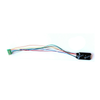
Illustrates NMRA 8-pin plug connection and describes wire color codes for functions.

Hard-wiring Decoders

Provides guidance on hard-wiring decoders and insulating connections with heat shrink.

Capacitor Removal

Recommends removing original suppression parts for better running quality.

Function Wire Details

Wiring and Function Color Codes

Details function wire colors and their remapping capabilities for lighting and accessories.

Blue Common Wire

Explains the blue wire as the common positive for all functions.

Function 1 (White Wire)

Describes the white wire's default use for front lights and its operation via F0 or 'Light'.

Function Wire Settings

White Wire Settings (CV49, CV34, CV64)

Details CVs for controlling white wire behavior, button mapping, and dimming.

Yellow Wire Settings (CV50, CV35, CV64)

Details CVs for controlling yellow wire behavior, button mapping, and dimming.

Green Wire Settings (CV51, CV36, CV64)

Details CVs for controlling green wire behavior, button mapping, and dimming.

Function Wire Settings (Continued)

Purple Wire Settings (CV52, CV37, CV64)

Details CVs for controlling purple wire behavior, button mapping, and dimming.

Changing Function Behavior

Explains how to modify function actions and activate special light effects.

Function Button Mapping

Explains how functions can be re-allocated to different function buttons for greater flexibility.

Function Mapping CVs

Details CVs (33-38) and their default values for mapping functions to buttons 1-12.

Motor Control Tuning

Tuning Motor Control

Guide to adjusting motor control CVs for optimized locomotive performance.

Motor Control CVs (CV2-CV6)

Details CVs for starting voltage, acceleration, deceleration, top speed, and mid speed.

Real-World Running Simulation

Discusses simulating real-world locomotive behavior through CV adjustments.

Configuration Examples and Options

Recommended Setups

Provides recommended CV settings for different locomotive types (DMU, Diesel, Steam).

Back EMF Options

Explores advanced Back EMF controls like disabling by speed step or button control.

Other Useful Features

Highlights additional non-standard functions that enhance realism and versatility.

Advanced Control and Lighting

Motor Button Control

Explains controlling motors with function buttons and setting motor speed.

Rule 17 Lighting Control

Detailed guide to implementing Rule 17 lighting for realistic headlight dimming.

Rule 17 Setup Steps

Provides step-by-step instructions for setting up Rule 17 lighting using CVs.

Advanced Configuration and Locking

Rule 17 CV Settings (CV49, CV50)

Instructs to set CV49 and CV50 to 40 for Rule 17 always on functionality.

Speed Tables

Explains user-editable speed tables in 28 steps and their activation.

Locking the Decoder

Guides on locking and unlocking decoders for multi-unit sets using CV15 and CV16.

Initial Decoder Setup for Locking (CV16)

Instructs to assign unique CV16 numbers to decoders before locking.

CV29 and Troubleshooting

CV29 Explained

Comprehensive guide to CV29, its functions, and common settings.

CV29 for Short/Long Addresses

Provides specific CV29 values (6/38) for short and long address configurations.

Troubleshooting

Covers common issues like no response, lighting problems, and CV mistakes.

Related product manuals