Lake Shore Model 102 User’s Manual
4-2 Service
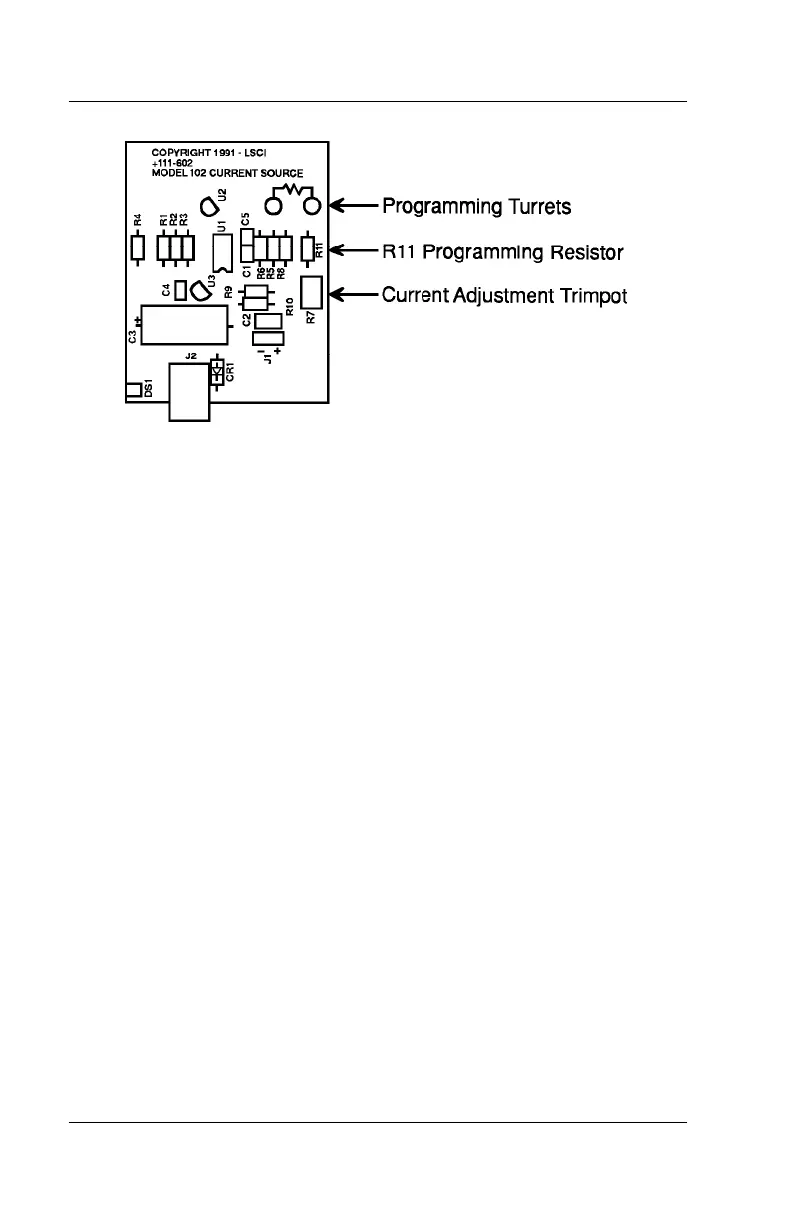
P-201-4-1.bmp
Figure 4-1. Model 102 PCB Layout
4.2.1 Current Calibration
To calibrate output current using the DC Ampere Range of a digital
multimeter (DMM), use a DMM with 4-digit resolution or better and a 100 k
Ω
load resistor.
NOTE: If the output current has been reprogrammed to a value other than
the factory preset 10 µA, use a load resistor of the same value as the new
programming resistor. Calibration accuracy is limited to DMM current
measurement accuracy.
1. To open the unit, remove the four rubber feet and four screws from the
bottom of the unit. Gently separate the top half of the enclosure from the
bottom half and front panel.
2. Connect one end of the load resistor to the front panel +CURRENT
OUTPUT
terminal.
3. Connect the DMM HI terminal to the other end of the load resistor and
the DMM LO terminal to the
–CURRENT OUTPUT terminal.
4. Select DC Amperes on the DMM.
5. Adjust the CURRENT ADJ trimpot on the Model 102 circuit board until
the DMM reads 10.000 µA
NOTE: If output current has been reprogrammed to another value, adjust to
that value.
6. Replace top of enclosure, screws, and feet. Resume normal operation.