CAUTION
Hazardous voltages may be present on the terminal block or inside the J1
connector ON UNITS WITH OUTPUTS ABOVE 50VDC. Insure unit is
powered off and disconnected prior to servicing. Refer to Section 1.2
The power supply could be configured for either Local or Remote programming. The supply
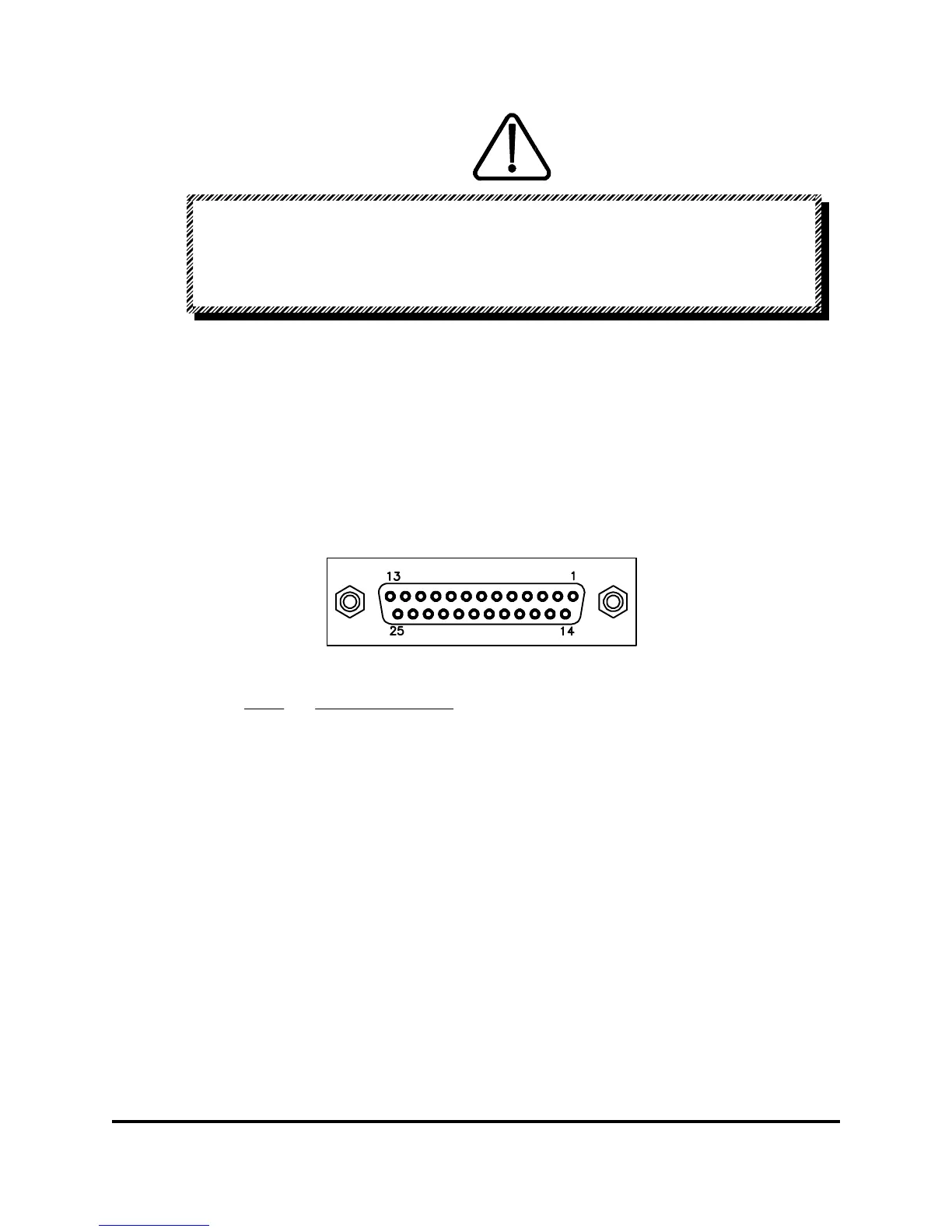
is programmed by the shorting connections on terminal strip TB1, or J1 (the 25 Pin “D” shell
connector) located on the rear panel (See Figure 3.3). The terminal designations of TB1 are
silk screened. Refer to Table 3.2 for Terminal/Pin designations. In Local programming, the
power supply is controlled by the front panel's Voltage and Current Knobs. Remote
programming (externally controlled at TB1or J1) is done by the following:
A. External resistance
B. External DC Voltage
C. External DC Current
Figure 3.3 Rear Panel “D” Connector
Remote Dry Contact Turn On (Remote SW)16 & 17
Remote Voltage Turn On (Remote V IN)15 & 16
+ Shunt (+I)14
Inverted I Amplifier In13
- Shunt (-I)12
Current Programming Resistance (I PROG R)11
Current Amplifier (I AMP IN)10
Current Programming Current (I PROG I)9
- Voltage (-V)8
- Voltage Remote (-V REM)7
Voltage Programming Resistance Common (V PROG R COM)6
Voltage Programming Resistance (V PROG R)5
Voltage Amplifier (V AMP IN)4
Voltage Programming Current (V PROG I)3
+ Voltage Remote (+V REM)2
+ Voltage (+V)1
PIN DESCRIPTIONPIN #
83-473-000 Revision J
3 - 3 Operating Instructions