CAUTION
An opening in the remote programming circuit is effectively a high
programming resistance and will allow an uncontrolled voltage rise
exceeding the maximum output of the power supply. This may cause
possible damage to the power supply and/or load. For this reason, any
programming resistor switcher must have shorting contacts. This type of
shorting switch connects each successive position before disconnecting
the preceding one.
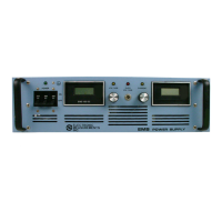
B External DC Voltage:
A variable voltage programs the output from zero to full rated voltage. Configure the
strapping connections on TB1/J1 as shown on Figure 3.6
1. Remove the jumpers between terminals TB1-3, TB1-4 and TB1-5 or J1-3, J1-4 and J1-5.
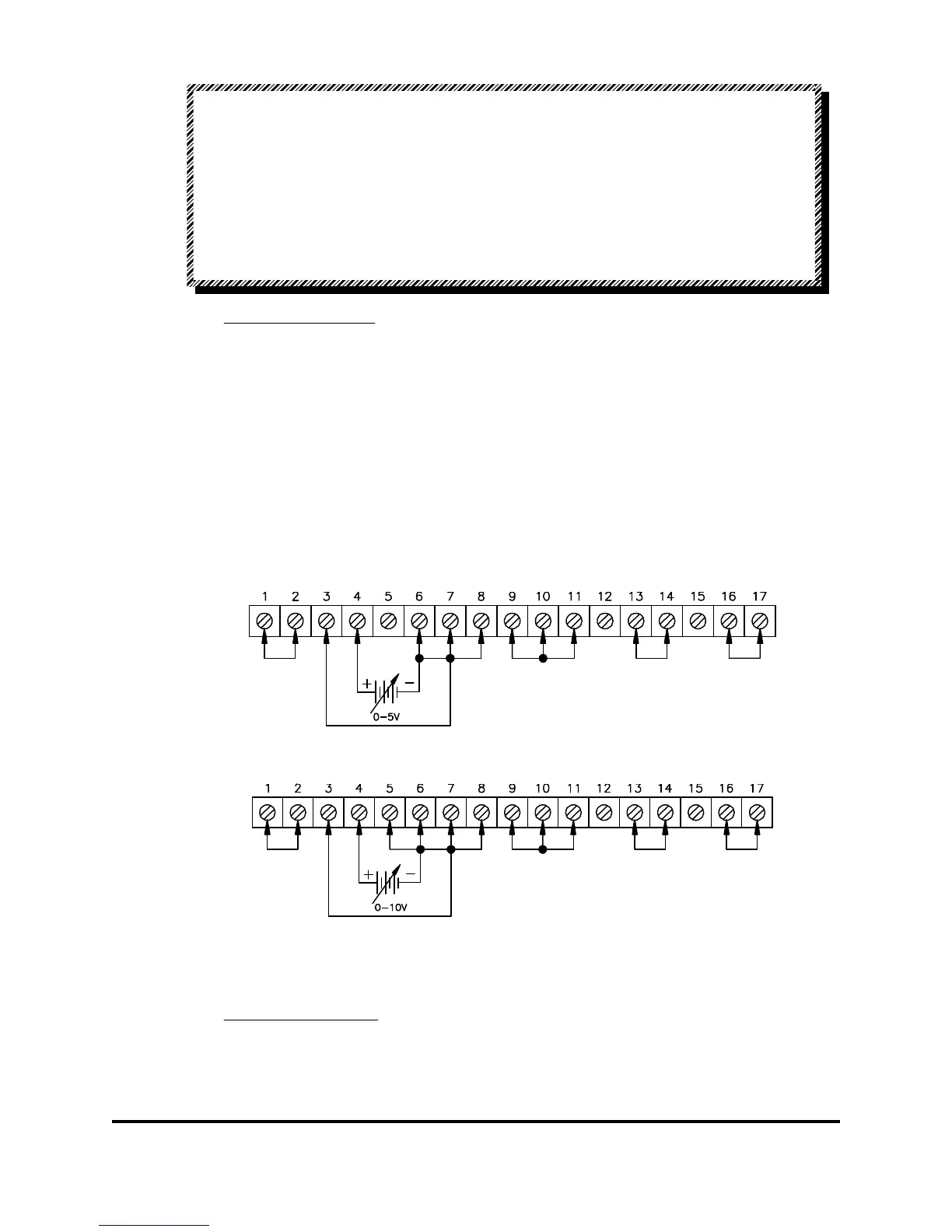
2. If unit has the 0 to 10 V programming option, connect a link between TB1/J1-5 and
TB1/J1-6 as shown in Figure 3.6b. Otherwise, if the unit has the default 0 to 5 V
programming connect as shown in Figure 3.6a.
3. Connect the programming voltage source between TB1/J1-4 (positive) and TB1/J1-6
(negative).
NOTE: Apply the appropriate programming voltage. Do not apply 0-10V programming
to a unit that has the default (0-5V) programming.
Figure 3.6a: Remote Programming by External Voltage, Voltage Mode
Figure 3.6b: Remote Programming by External Voltage,
Voltage Mode (as per 0 - 10V Option).
C. External DC Current:
A current of 0 to 1mA programs the output from zero to full rated voltage. Configure the
strapping connections on TB1 or J1 as shown on Figure 3.7.
83-473-000 Revision J
3 - 6 Operating Instructions