14
6 Appendix
6 Appendix
6.1 Layout of the Operational Controls
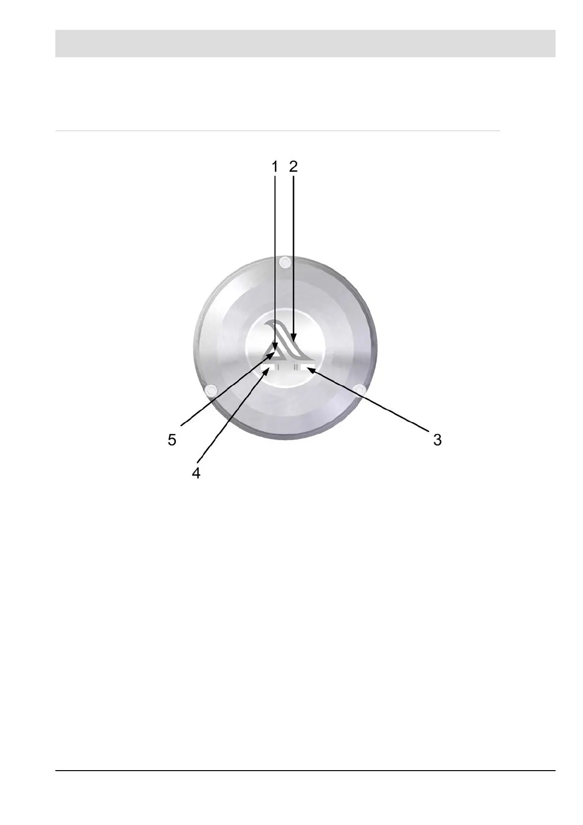
Fig. 6-1 Monitoring and control elements F200K2
1 LED (green): Indication, ’Flame in’ state
2 Intensity indicator for flame signal in the range 0 ... 100 %
3/4 LED (yellow), only for F200K2, lights for active range.
5 LED (red): Indication, "Flame out state"
 Loading...

