55
4 Appendix
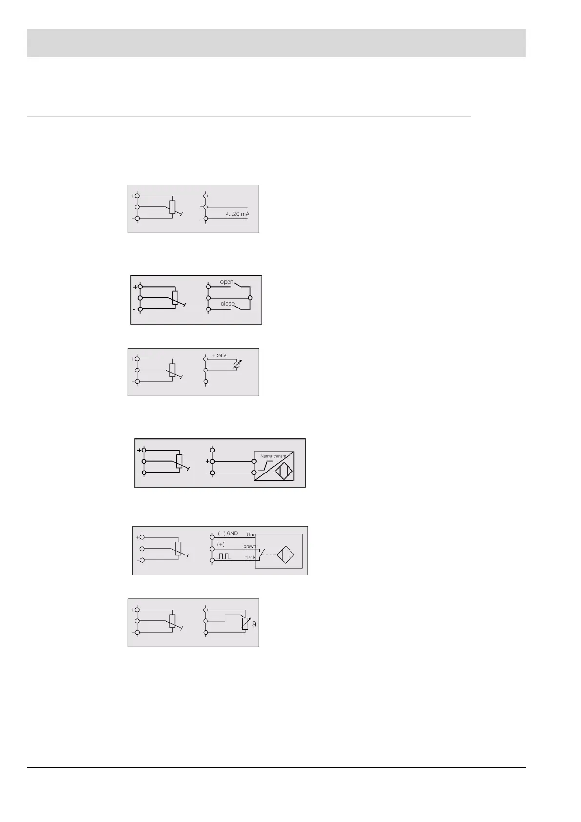
4.3 Wiring of the Analogue Inputs
The following circuit diagrams are universal. They do not refer to the use of the respective
channels. In addition all analog inputs (except correction) are drawn for potentiometer connec-
tion. If current is used as input quantity on some channels, the respective inputs have to be
wired as shown below. Where current is used as feedback signal in place of a potentiometer:
Where a three-point step signal from the load control unit is used as load input, the contacts
are to be connected as follows in place of the load potentiometer:
Where a 4 ... 20 mA unit is to be supplied with 24 V.
Where the speed feedback is not by way of 0/4 ... 20 mA but through integral speed sensing
(direct switching of a Namur transmitter)
Where the speed feedback is not by way of 0/4 ... 20 mA but through integral speed sensing
(iductive sensor with three wire system)
Where an input is configured as PT 100.
The pin-compatible 6 60 R 0131 relay module may also be used Instead of the 6 60 R 0013
relay module shown.
If the 6 60 R 0019 is used instead for the actuation of DC motors, terminal 4 of the relay mod-
ule must also be connected to terminal 31 of the FMS.
The digital signals can also be pre-set via the 230 V signal input module instead of via floating
contacts (6 60 R 0018)
.

 Loading...

