12
3 Product Description
3.3 Equipment
With respect to the electrical equipment, the pilot burner is available in 3 versions.
The versions differ as follows:
Fig. 3-4 Pilot burner versions A-B-C
1
IFM= ionisation flame scanning
2
either ignition transformer or IFM
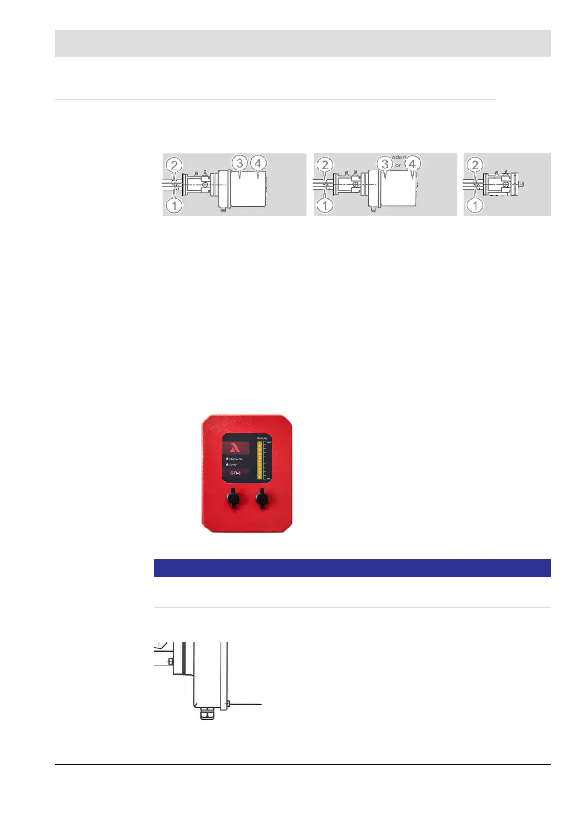
GFI 48 / 70 / 89 with optional bar graph
Fig. 3-5 Optional GFI housing with bar graph equipment
NOTICE
The bar graph is optional for versions A and B (if with IFM).
No bar graph available in Ex-area
Differences in the type of cable entry point
Equipment Design A
(standard)
Design B Design C
1 Ignition electrode X X X
2 Ionisation electrode X X X
3 Ignition transformer X X
2
4 Flame scanner
(IFM)
1
X X
2
The connection cables are fed into the device enclosure either
via a screwed cable gland or via a plug-in connection. The differ-
ence is in the flexibility during installation and connection work.
There are no differences in terms of technology or functionality.
In these operating instructions, the device is always depicted
with screwed cable gland.