38
5 Commissioning
5.2.1 Electrically Connecting the GFI Pilot Burner
Design A: Electrically connect the pilot burner
Design B: Electrically connect the pilot burner
NOTICE
Version B has the same connection as version A.
For version B however, the following applies:
If only the ignition transformer is used, only connect wires 3,4 and PE.
With an external flame scanner, the ionisation cable should be connected to wire 6
The remainder is without function. If only the IFM is used, only connect wires 1,2,5,6 and PE.
Connect the pilot burner
cables as follows
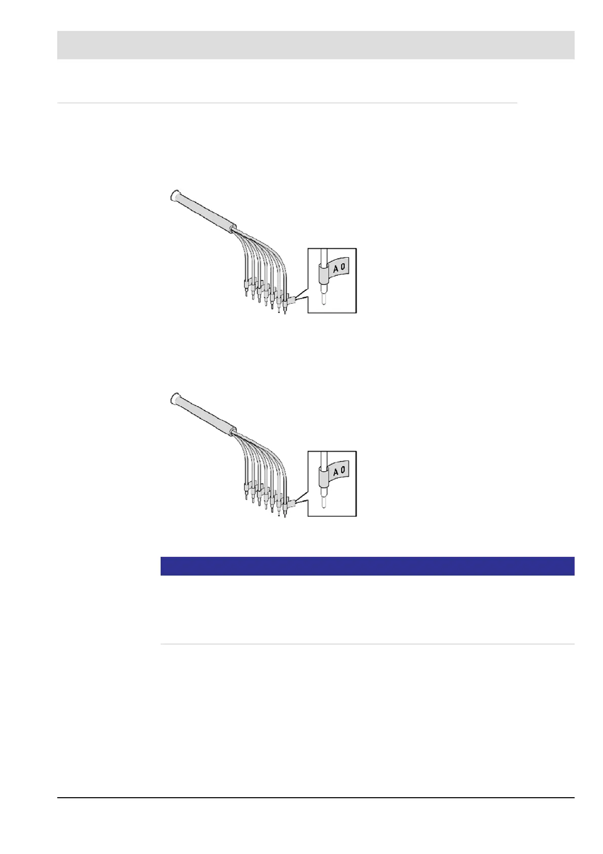
Fig. 5-10 Connect pilot burner version A
No. Wire colour Function
1 bl Phase
2 bl Neutral conductor
3 bl Ignition transformer N
TR
-N
4 bl Ignition transformer L
TR
-L
5 bl COM
6 bl NO
PE gn/ye Protective conductor
Fig. 5-11 Electrically connect the pilot burner
design B
No. Wire colour Function
1 bl Phase
2 bl Neutral conductor
3 bl Ignition transformer N
TR
-N
4 bl Ignition transformer L
TR
-L
5 bl COM
6 bl NO/ionisation electrode
PE gn/ye Productive conductor