Do you have a question about the Lancaster 7-LETCT-1B and is the answer not in the manual?
Specifies the acceptable pressure range for the water filter system.
Defines the acceptable temperature range for the water filter unit.
Details the current draw and voltage requirements for the unit.
Warns against hydrocarbons and use for critical health applications.
Covers lubrication, fitting tightening, Teflon tape use, and tool recommendations.
Addresses local codes, drain line requirements, and electrical connections.
Explains valve settings for downflow/upflow and regeneration modes.
Lists filter models, mineral tank sizes, and mineral quantities.
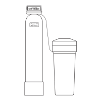
Advises on choosing an installation location and preparing for the unit.
Step-by-step guide for adding filter minerals to the tank.
Instructions for installing the 5/8" poly tube drain line and its connection.
Emphasizes proper drain line routing, air gaps, and avoiding direct sewer connections.
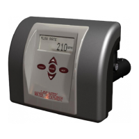
Guides on setting the current time on the system's display.
Explains time reset after power loss and meaning of error codes.
Instructions to set the backwash start time and frequency.
Details the process of filling the unit and initiating the first backwash.
Illustrates bypass valve positions: Bypass, Diagnostic, Normal, Shut Off.
Maintenance advice for Calcite-based acid neutralizers, including monitoring level.
Guidelines for Birm filters, covering water quality requirements and pH adjustment.
Instructions for Carbon filters, focusing on periodic backwashing and eventual replacement.
Information on Filter AG media for sediment removal and backwashing needs.
Lists and describes parts making up the drive assembly.
Explains the roles of the PC board and motor in controlling valve operations.
Instructions for removing drive gears and their cover.
Steps for detaching the PC board and drive bracket from the valve.
Detailed steps for safely detaching the motor from the drive bracket.
Explains how pistons are controlled by the PC board for valve cycle positions.
Describes the spacer stack assembly's design and sealing mechanisms.
Details the injector's function in drawing and mixing regenerant with water.
Explains the refill flow control assembly's role in managing regenerant tank refill rate.
Instructions for removing and reinstalling the meter plug assembly.
Guides on working with the bypass valve rotor and handle installation.
Steps to reset the valve electronics after bypass valve servicing.
Illustrates the optional wrench's application for various valve parts.
Lists components for PVC and brass elbow and sweat assemblies.
Details individual parts of the BP2000 Bypass Valve.
Lists optional fittings and adapter assemblies available for the system.
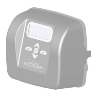
Lists parts related to the front cover, motor, and drive bracket.
Lists components for the drive cap, pistons, and spacer stack assembly.
Lists parts for the injector cap, screen, and associated O-rings.
Lists the parts included in the meter plug assembly.
Details parts for the 3/4" drain line and proper DLFC orientation.
Lists parts for the brine refill elbow and polytube insert.
Addresses problems with the timer not displaying time correctly.
Solutions for regeneration occurring at the wrong time of day.
Diagnoses error messages (E1-E3) and unexpected stalls during operation.
Resolves issues where the valve fails to regenerate automatically.
| Brand | Lancaster |
|---|---|
| Model | 7-LETCT-1B |
| Category | Water Dispenser |
| Language | English |