2
Provide an adequate potable water supply. Water pipe connections and xtures directly connected to a potable water supply must
be sized, installed, and maintained according to federal, state, and local laws. The water supply line must be at least a 3/8 inches
(9.525 mm) pipe with a minimum of 25 PSI (0.172 MPA) line pressure, but not exceeding a maximum of 50 PSI (0.345 MPA).
Water pressure exceeding 50 PSI (0.345 MPA) must be reduced to 50 PSI (0.345 MPA) with the provided pressure regulator. Use
a lter in the water line to avoid equipment damage and beverage o-taste. Check the water lter periodically, as required by local
conditions. The water supply must be protected by means of an air gap, a backow prevention device or another approved method
to comply with NSF standards. A leaking inlet water check valve will allow carbonated water to ow back through the pump when it
is shut o and contaminate the water supply. Ensure the backow prevention device complies with ASSE and local
standards. It is the responsibility of the installer to ensure compliance.
! Water Notice
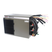
SPECIFICATIONS
DIMENSIONS
Width: 27.125 inches (690 mm)
Depth: 27.25 inches (946 mm)
Height: 31.25 inches (790 mm)
WEIGHT
Shipping: 340 lbs (154.22 kg)
Operating: 457 lbs (207.30 kg)
Ice Bath: 50-55 lbs (23-25 kg)
Water Bath Capacity: 21 gallons
(79 liters)
CARBON DIOXIDE (CO
2
) SUPPLY
Min Pressure: 70 PSIG (0.483 MPA)
Max Pressure: 80 PSIG (0.552 MPA)
FITTINGS
Water from Carbonator Inlet: 3/8” barb
Plain Water Inlet: 3/8” barb
Brand Syrup Inlets: 3/8” barb
ELECTRICAL
230-240 VAC / 50-60 Hz / 2.6 Amps
PLAIN WATER SUPPLY
Min Flowing Pressure: 25 PSI (0.172 MPA)
Max Static Pressure: 50 PSI (0.345 MPA)
CARBONATED WATER SUPPLY
Min Flowing Pressure: 35 PSI (0.241 MPA)
Max Static Pressure: 60 PSI (0.414 MPA)
This unit emits a sound pressure level below 70 dB
INSTALLATION
Unpack the Dispenser
1. Cut plastic band and remove.
2. Remove top portion of carton by lifting up.
3. Remove top inner carton pad and corners.
4. Remove accessory kit of loose parts from drip tray.
5. Lift unit up by plywood shipping base and remove lower
portion of carton.
Inspect unit for concealed damage. If evident, notify
deliveringcarrierandleaclaimagainstthesame.
NOTE
Ifunitistobetransported,itisadvisabletoleavethe
unitsecuredtotheplywoodshippingbase.
NOTE
DO NOT LAY UNIT ON ITS SIDE OR BACK.
! ATTENTION
6. Remove plywood shipping base from unit by moving unit so
that one side is o the counter top or table allowing access
to screws on the bottom of the plywood shipping base.
7. If leg kit has been provided, assemble legs by tilting unit.
Your Service Agent:
Service Agent Telephone Number:
Serial Number:
Model Numer:
ThismanualwasdevelopedbytheLancerCorporationasareferencefortheowner/operatorandinstallerofthis
dispenser.Pleasereadthisguidebeforeinstallationandoperationofthisdispenser.Ifserviceisrequiredpleasecallyour
LancerServiceAgentorLancerCustomerService.Alwayshaveyourmodelandserialnumberavailablewhenyoucall.
READ THIS MANUAL
 Loading...