3
Leave12inches(305mm)ofextratubingbelowthe
counterforservicingandmovingthedispenser
NOTE
Selecting/Preparing Counter Location
4. Condenser air is drawn in from the front half of the top cover,
and discharged out the rear half of the top cover. A minimum
of eight (8) inches (203 mm) clearance must be maintained
over the top of the unit to provide for proper air ow and
circulation.
Unit Installation
1. Remove bonnet and front plate from the unit.
2. Route appropriate tubing from the syrup pump location to the
syrup inlets. Connect tubing to inlets using the oetiker pliers
and ttings. Repeat for all syrup connections.
4. Flush water supply line thoroughly.
7. Using a conductivity meter, measure the electric conductivity
of the distilled water mixture.
Failuretomaintainspeciedclearancewillcausethe
compressortooverheatandwillresultincompressor
failure
! ATTENTION
Carefullyreadthisbeforellingthewaterbathtank.
Inordertooptimizethemaximumperformanceofthe
dispenser,thefollowingMUSTbeadheredto:
! CRITICAL - to maximize performance
Forproperfunctionoftheelectronicicebankcontrol
thetotaldissolvedsolids(TDS)measurementsshould
be300-500ppm.
! ATTENTION
TheE.C.measurementofthedistilledwatermixture
mustbebetween100and300uS/cm.Below100uS/cm,
thecompressorwillnotworkproperlyandabove300
uS/cmcouldcausethelinestofreeze.
! ATTENTION
NSFlistedunitsmustbeinstalledwithlegsprovided.
NOTE
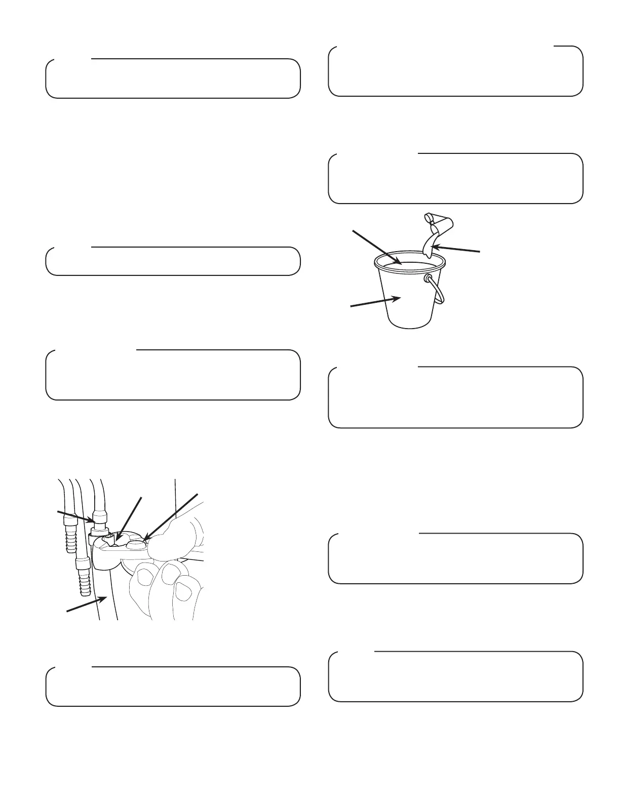
5. Insert water line into a large bucket, and ll with approx. 5.4
gallons (20.4 L) of distilled water.
6. Add 1/8 oz (4 g) of baking soda to distilled water and stir.
1. The unit is designed to sit on a at, supported surface
capable of supporting a minimum weight of 400 lbs (182
kg). Select a location that is in close proximity to a properly
grounded electrical outlet and a water supply that meets the
requirements shown in the Specications section found on
previous page.
2. Select a location for the syrup pumps, CO
2
tank, syrup
containers, water lter (recommended), and remote
carbonator.
3. The unit is designed to be mounted with legs. If leg kit has
been provided, assembly legs by tilting unit.
Thedispensershouldonlybeinstalledinalocation
whereitcanbeoverseenbytrainedpersonnel
NOTE
A
B
C
A. Oetiker Pliers
B. Fitting
C. Tubing
D. Syrup/Water/CO
2
Inlet
D
3. Route appropriate tubing from the water source to the
compressor deck ll hole, identied by the yellow cap, and
ONLY connect tubing to water source.
A
B
C
A. Bucket
B. Distilled Water
(approx. 5.4 gal)
C. Baking Soda
(approx. 1/8 oz)
UsethePlumbingDiagramsonpages12-15to
determinewhichvalvesaretobeplumbedwithplain
waterorcarbonatedwater
NOTE
8. Remove yellow cap from the water bath ll hole and insert
and insert a funnel into the ll hole.
9. Remove the insulation strip from front of the refrigeration
deck.
10. Carefully pour the distilled water mixture into the water bath
tank until water ows out of the overow tube at the front of
the unit. (Repeat steps 9-11 if needed)
Thewaterbathcompartmentmustbelledwithwater
beforepluggingintheunit,otherwisethecompressor
fan may not operate properly.
! ATTENTION
11. Replace yellow cap, replace insulation, then connect water
line to the carbonated water inlet in the front of the unit.
12. If plain water is to utilized for any of the valves, install a “U”
tting to the water line and connect to plain water inlet.
 Loading...