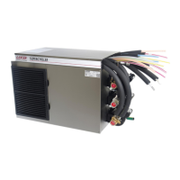
4
Leave12inches(305mm)ofextratubingbelowthe
counterforservicingandmovingthedispenser
NOTE
Thelengthofthepythonmustnotexceed25feet(8
meters)ifbuilt-insyruppumpsarebeingused.
NOTE
Ifplainwaterisnotwanted,removethebarbedtting
andshortextensiontting,cancapendofplainwater
linewithcapfromaccessorykit.
NOTE
Theindividualbarbedttingsforthelinescanbe
removedforinsertionintothepythontubingby
removingthe“U”shapedretainerpinandpullingthe
ttingoofthesyrupline.
NOTE
Ifplainwaterisnotwanted,spliceastainlesssteel,
reducing,barbedhosetee(PN01-0527)inthe3/8inch
sodaline.Useaseparate1/4inchtubetocompletethe
connectionfromthebarbedteetothetowermanifold.
NOTE
DONOTinsulateconnectionsatthistime.Leaveall
connectionsexposedforinspectionofleaks.
NOTE
14. Turn on water supply and check for leaks
15. Plug in the unit to a grounded electrical outlet then turn the
unit on to begin building an ice bank.
Thedispensermustbeproperlyelectricallygrounded
toavoidseriousinjuryorfatalelectricalshock.The
powercordhasathree-pronggroundedplug.Ifa
three-holegroundedelectricaloutletisnotavailable,
useanapprovedmethodtogroundtheunit.Followall
localelectricalcodeswhenmakingconnections.Each
dispensermusthaveaseparateelectricalcircuit.Do
notuseextensioncords.Donotconnectmultiple
electricaldevicesonthesameoutlet.
! WARNING
13. Route appropriate tubing from the syrup pump location to the
CO
2
inlet and connect tubing to CO
2
inlet.
Installing Remote Syrup Pumps
1. Install BIB rack and remote pumps according to manufactur-
ers’ instructions.
2. Once pumps and BIB rack are installed, measure and cut
tubing to length between the pump CO
2
inlets, then connect
tubing to all pumps.
Installation to Dispenser
1. Determine the appropriate length of insulated python tubing
required, allowing additional length as required for servicing.
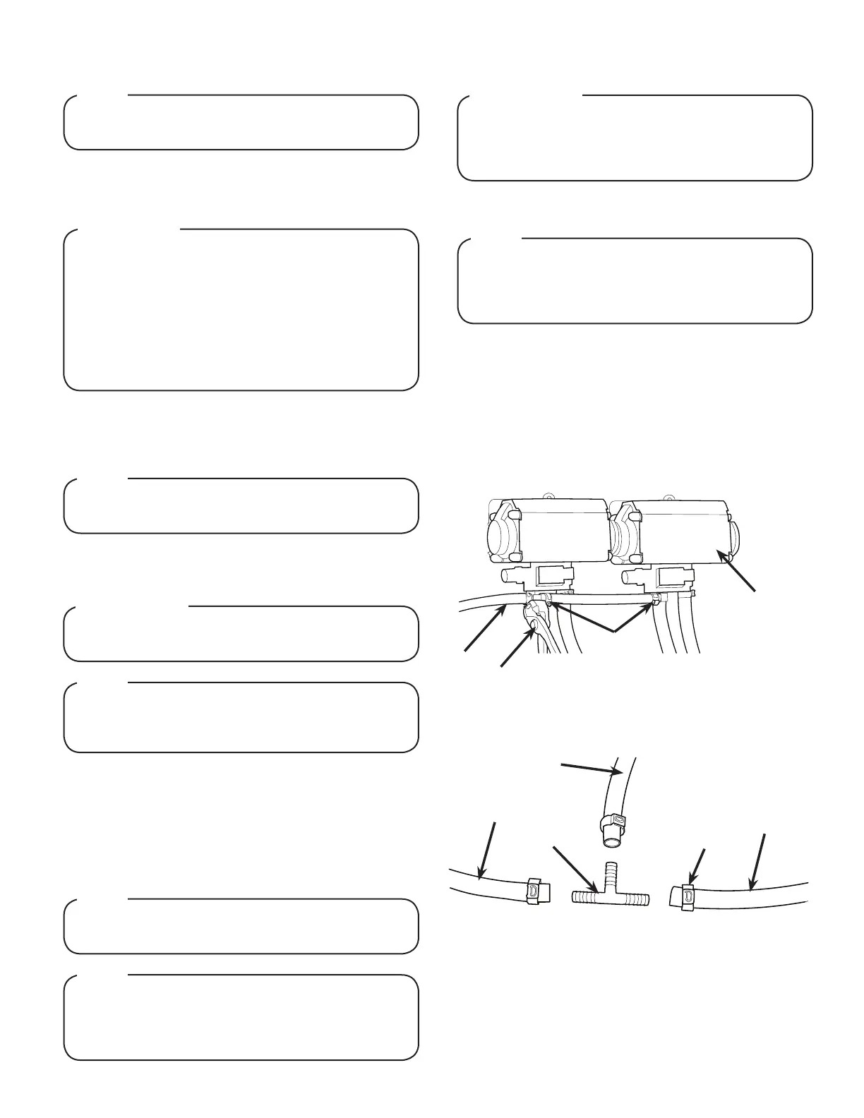
A
B
C
A. Syrup Pump
B. CO
2
Line
C. Fitting
D. Oetiker Pliers
D
3. Using tubing cutters, cut any pump CO
2
supply line and
install tee tting, then route appropriate tubing from the CO
2
supply to the tee tting at syrup pumps.
A. Tee Fitting
B. Line to Syrup Pump
C. Fitting
D. Line to CO
2
Supply
A
B
B
C
D
4. Cut tubing from CO
2
supply to tee tting at syrup pumps and
install another tee tting.
5. Attach line from dispenser CO
2
inlet to tee tting between
syrup pumps and CO
2
supply.
6. Connect tubing from dispenser syrup inlet to the syrup pump
outlet tting. Repeat for each syrup line/pump.
2. Position one end of the python near remote unit. Using a
sharp knife or razor, slit the python insulation back 18 inches
(46 cm) and roll insulation back to expose individual tubes.
3. Slide the tube insulation (from the accessory kit) over one of
the 3/8 inch soda lines in the python then connect line to the
90° elbow on the inlet to the recirculating pump.
4. Connect the other 3/8 inch soda line from the python to the
return inlet on the front of the unit.
5. Connect each of the 1/4 inch syrup/plain water lines to the
syrup/plain water inlets on the front of the unit.
6. Route the opposite end of the python to tower. Determine
the length required and cut if necessary.
7. Slit the python insulation back 12 inches (30 cm) and roll
insulation back to expose individual tubes.
8. Connect each of the lines from the python to the syrup, soda,
and plain water ttings on the tower manifold.
Carefulnottocuttubingbundlewhenslittingpython
insulation.
! ATTENTION
Useasharpknife,razorblade,ortubecuttertocut
tubing.Tubingcutwithasawwillresultinplastic
shavings,whichwillplugtheowcontrolsinthe
dispensing valve.
! ATTENTION
 Loading...