5
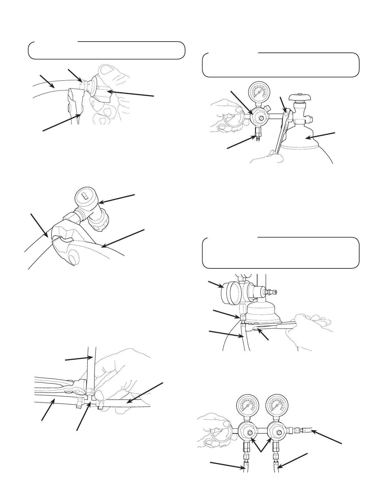
7. Install BIB (bag in box) connectors onto the syrup pump inlet
tubing.
Useproperconnectorforsyrupmanufacturer
! ATTENTION
A. Syrup Pump Inlet
B. Fitting
C. BIB Connector
D. Oetiker Pliers
A
B
C
D
8. Connect syrup BIBs to connectors. Repeat for each syrup
line/pump.
Installing CO
2
Supply / Dispenser Setup
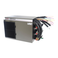
1. Connect high pressure CO
2
regulator assembly to CO
2
cylinder or bulk system.
2. Connect a 1/4” nut, stem and seal to CO
2
regulator outlet.
3. Route appropriate tubing from the low pressure CO
2
regulator manifold location to the 1/4” nut, stem on the high
pressure CO
2
regulator attached to source and connect
tubing.
Beforeinstallingregulator,assurethataseal(washer
oro-ring)ispresentinregulatorattachmentnut.
! ATTENTION
A
B
C
A. Tee Fitting
B. Line to Tee at Figal Tank
C. Dispenser CO
2
Inlet
D. CO
2
Supply
D
6. Connect tubing from dispenser syrup inlet to the gal syrup
outlet tting. Repeat for each syrup line/tank.
Connecting to Syrup Supply - Figal Syrup Tank
1. Connect tubing routed from CO
2
inlet in dispenser to gal
syrup tank CO
2
inlet.
2. Using tubing cutters, cut line from CO
2
inlet to gal syrup
tank and install tee tting, then route appropriate tubing from
second gal syrup CO
2
inlet to tee tting.
3. Repeat step 2 for remaining gal syrup tanks.
4. Cut tubing from dispenser CO
2
inlet to tee tting at gal
syrup tanks and install another tee tting.
5. Route appropriate tubing from CO
2
supply to tee tting
between dispenser CO
2
inlet and gal syrup tanks and
connect tubing to tee tting.
A
B
C
A. Figal Connector
B. Line From CO
2
Inlet
C. Oetiker Pliers
- Thread regulator nut on to tank, then
tighten nut with wrench
A. CO
2
Regulator
B. Outlet
C. Wrench
D. CO
2
Supply
A
B
C
D
A. CO
2
Regulator
B. 1/4” Nut, Stem & Seal
C. Line to Syrup Pumps
D. Oetiker Pliers
A
B
C
D
AdedicatedCO
2
regulatorisrequiredtosupplytheCO
2
inletattheunitaswellastoallsyruppumps/remote
pressurizedsyrupsupplytanks.
! ATTENTION
4. Connect tubing routed from the CO
2
inlet at the unit to one of
the low pressure CO
2
regulator manifold outlets.
5. Connect tubing routed from the tee at the syrup pumps to
the second outlet of the low pressure CO
2
regulator manifold.
A
B
C
D
A. Line to CO
2
inlet at Unit
B. Line to Syrup Pumps
C. Line to CO
2
Regulator
D. CO
2
Regulator Manifold