22
Section 3: Adjustments
FSP300, FSP500, FSP700 & FSP1000 Broadcast Spreaders 309-065M
Table of Contents
11/19/24
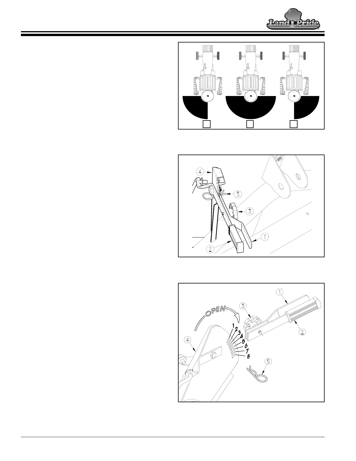
Dispersal Pattern
Refer to Figure 3-1, Figure 3-2 & Figure 3-3:
Product dispersal is controlled by properly opening and
closing left and right gates at the hopper bottom with
adjustment levers (#1 & #2).
Some adjustment to the distributor vanes may be
required. See detailed instructions for “Distributor Vane
Adjustment” on page 23.
Positioning right and left gate levers as follows:
Left Side Dispersal, View (A) in Figure 3-1
Refer to Figure 3-3:
1. Remove lever locking knob (#3).
2. Close right gate by moving adjustment lever (#1)
above gate setting position #1.
3. Move adjustment lever (#2) to the selected gate
setting provided in spreading charts on page 24 for
lbs/acre and page 25 for kgs/hectare.
4. Secure adjustment lever (#2) by placing hair pin
cotter (#5) in the selected gate setting hole with
adjustment lever (#2) resting on top of hairpin (#5).
Full Width Dispersal, View (B) in Figure 3-1
Refer to Figure 3-2 & Figure 3-3:
1. Lock adjustment levers (#1 & #2) together with lever
locking knob (#3).
2. Move adjustment levers together just above selected
gate setting provided in spreading charts on
page 24 for lbs/acre and page 25 for kgs/hectare.
3. Secure adjustment levers by placing hair pin
cotter (#5) in the selected gate setting hole with
adjustment levers resting on top of hairpin (#5).
Right Side Dispersal, View (C) in Figure 3-1
Refer to Figure 3-3:
1. Remove lever locking knob (#3).
2. Close left gate by moving adjustment lever (#2) up
above gate setting position #1.
3. Move adjustment lever (#1) to the selected gate
setting provided in spreading charts on page 24 for
lbs/acre and page 25 for kgs/hectare.
4. Secure adjustment lever (#1) by placing hair pin
cotter (#5) in the selected gate setting hole with
adjustment lever (#1) resting on top of hairpin (#5).
Delivery Direction
Figure 3-1
Lever Adjustments
Figure 3-2
Gate Setting Hole Numbers
Figure 3-3
Section 3: Adjustments


 To Next Page