12
Section 1: Assembly & Set-up
FSP500, FSP700 & FSP1000 Broadcast Spreaders 309-065M
Table of Contents
11/29/18
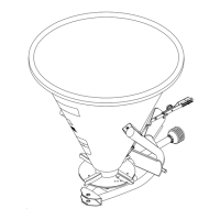
Check Driveline Minimum Length
Figure 1-8
Check Subcompact Tractor fit-up
Use instructions below when hooking-up a subcompact
tractor or Kubota BX tractor. If the tractor is a standard
size tractor, go to “Check Standard Tractor Fit-up” on
page 11.
Refer to Figure 1-8:
1. With driveline attached only to the spreadser, remove
outer driveline (tractor end) from inner driveline to
separate the two profiles.
2. Park tractor and spreader on a level surface.
3. Raise spreader until gearbox input shaft is level with
tractor power take-off shaft. Securely block spreader
at this height to keep the unit from lowering.
4. With spreader resting on the support blocks,
shutdown tractor using “Tractor Shutdown
Procedure” on page 9.
5. Attach outer driveline half to the tractor’s power take-
off shaft. Refer to “Driveline Hook-up” on page 10.
6. Hold inner and outer drivelines parallel to each other
as shown in Figure 1-6. Measure dimension “A”.
• If "A" is less than 2", continue with step 10.
• If “A” is greater than or equal to 2", continue with
step 7 below.
7. Remove outer driveline from the tractor and apply
multi-purpose grease to the inside of its outer shaft.
8. Reassemble the two driveline halves together.
9. Implement end of the driveline should still be
attached to the spreader gearbox. Hook-up tractor
end of the driveline to the power take-off shaft. See
“Driveline Hook-up” on page 10.
24976
IMPORTANT: A driveline that is too long can bottom
out causing structural damage to the tractor and
implement. Always check driveline minimum length
during initial setup, and when connecting to a
different tractor. More than one driveline may be
required to fit all applications.
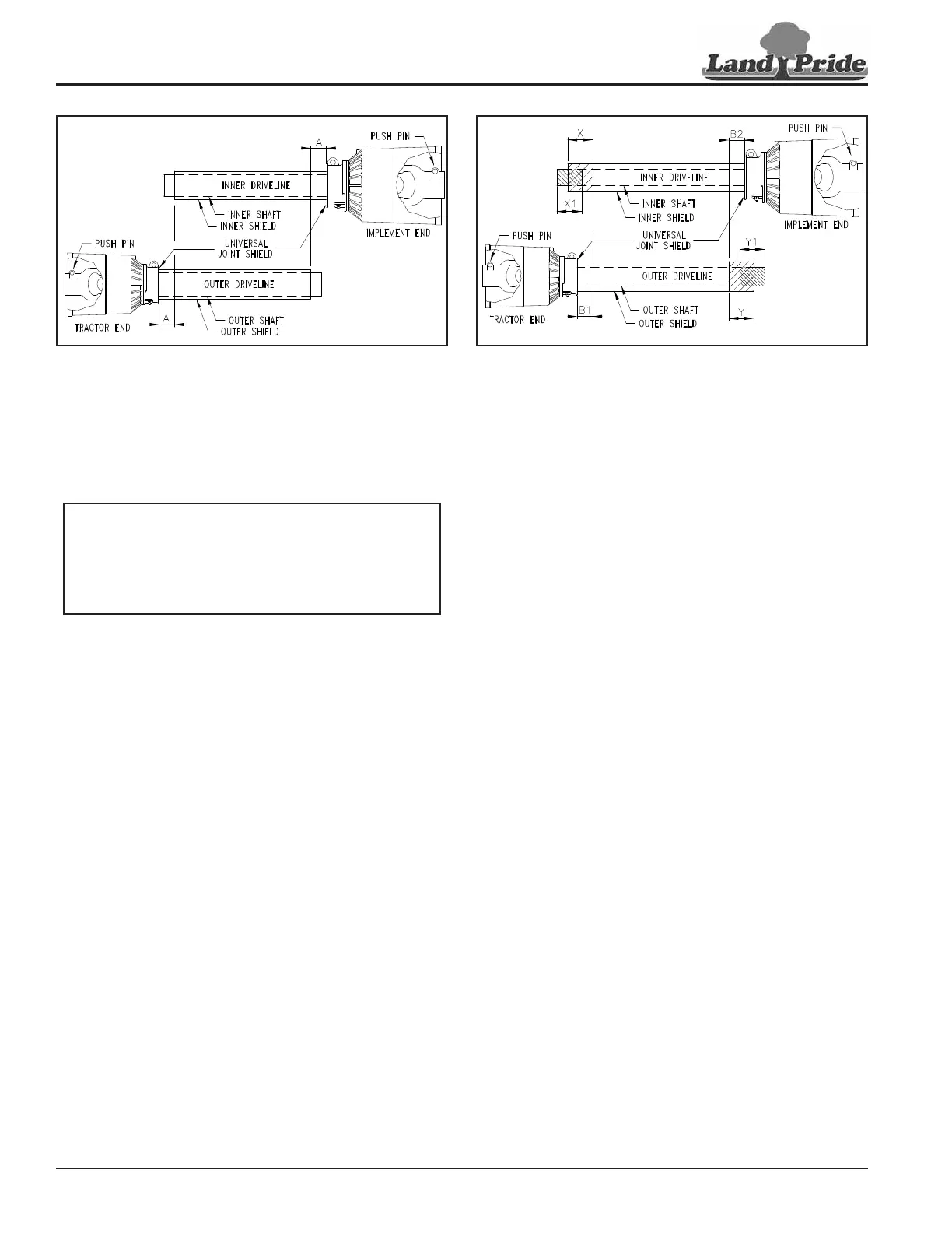
Shorten Driveline Length
Figure 1-9
10. If dimension “A” is less than 2", shorten driveline as
follows:
Refer to Figure 1-7:
a. Measure 2" (“B1” dimension) back from outer
driveline shield and make a mark at this location
on the inner driveline shield.
b. Measure 2" (“B2” dimension) back from the inner
driveline shield and make a mark at this location
on the outer driveline shield.
11. Remove outer driveline from the tractor power take-
off shaft and inner driveline from the spreader
gearbox shaft.
12. Cut off non-yoke end of inner driveline as follows:
a. Measure from end of inner shield to scribed mark
(“X” dimension) and record.
b. Cut off inner shield at the mark. Cut same amount
off the inner shaft (“X1” dimension).
13. Cut off non-yoke end of outer driveline as follows:
a. Measure from end of outer shield to scribed mark
(“Y” dimension) and record.
b. Cut off outer shield at the mark. Cut same amount
off the outer shaft (“Y1” dimension).
14. Remove all burrs and cuttings.
15. Apply multi-purpose grease to the inside of the outer
shaft and reassemble the driveline.
16. Attach driveline to the spreader and tractor. Refer to
“Driveline Installation” and “Driveline Hook-up”
on page 10.
24976
 Loading...