Installation and adjustament manual
26/26
REGULATION
7 EMISSION MEASUREMENT
This measurement must be performed in compliance local
regulations.
7.1 Idle emissions
CO limit ................................................ < / = 0.5% vol.
7.2 Fast idle emissions (2,000-2,500 RPM)
CO limit ................................................ < / 0 0.3% vol.
Lambda ............................................................1 ± 0.03
The emission verifications must be performed on both LPG
and petrol.
8 TROUBLE-SHOOTING
8.1 The engine stalls when entering idle
- Go to the screen MONITOR ECU as in Fig. 6.3.
- Determine whether the Lambda sensor signal is lean or
rich.
- Click on EXIT.
- View the ECU MANAGEMENT menu.
- Press F3.
- Start Adaptive Learn .
- In cell A, CORRECTIVE STEPS PERFORMED, enter
a number ranging between +15 and -15. The number is
to be positive if the lambda sensor show a lean signal,
or negative if the lambda sensor shows a rich signal.
Increase the number by a five step increment each time.
- Return to the ECU MANAGEMENT menu.
- Check for correct idle operation.
8.2 Uneven acceleration
If the engine idles properly but during acceleration the
RPMs do not increment smoothly, go to the screen ECU
PARAMETERS ⇒ ADAPTIVE LEARN and in the area
FUEL ENRICHMENT STRATEGY insert:
- a maximum negative value of -5 for rich Lambda sensor
signal
- a maximum positive value of +5 for lean Lambda sensor
signal
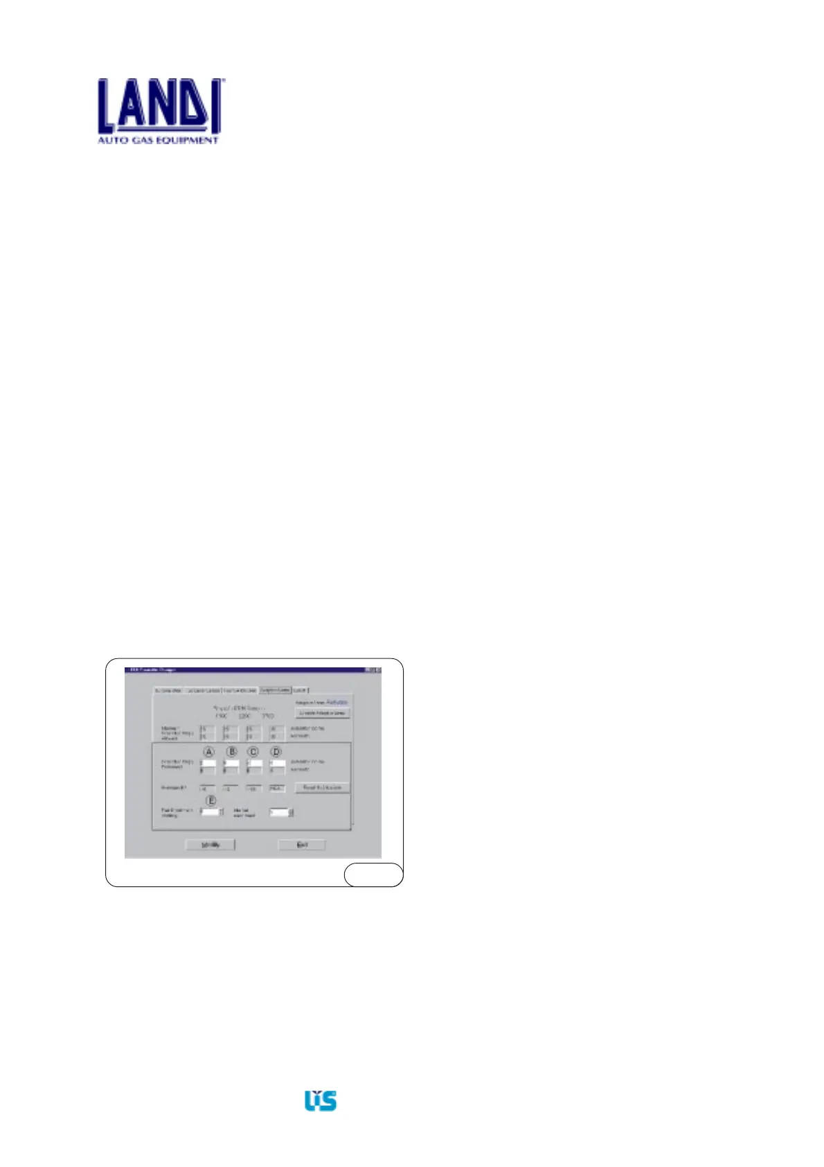
Fig.8.1
- Insert this value in cell E (see Fig.8.1) FUEL
ENRICHMENT STRATEGY.
- Click on the MODIFY button.
- Turn the ignition key off, then on.
8.3 Correct idle with non-optimized
integrator values
8.3.1 Integrator 1 out of the +10, -10 range
- From the menu MONITOR ECU go back to
ECU MANAGEMENT.
- Press F3
- Enter into ADAPTIVE LEARN (Fig.8.1).
- Algebraically sum the corrective steps of cell (A)
and the value AVERAGE DRIFT, and enter the
sum in cell (A). In this case 3, the sum is: -5+2=-3.
- Click on “Modify”.
- Turn the ignition key OFF, then ON.
- Wait for the change to take place.
- Return to MONITOR ECU menu.
- Integrator 1 must come close to the +10, -10 range.
8.3.2 Integrator 2 out of the +20, -20 range
- The following operation must be performed
during a road test.
- From the menu MONITOR ECU go back to
ECU MANAGEMENT.
- Press F3.
- Enter into ADAPTIVE LEARN (Fig. 8.1).
- Algebraically sum the corrective steps of cells
B-C-D to the value in the cell AVERAGE DRIFT
and enter it in cells B-C-D.
- In this case, only the 6,200 - 8,700 range is to be
corrected. Enter in cell (C): -15 - 2 = -17.
- Click on “Modify”.
- Turn the ignition key OFF, then ON.
- Wait for the change to take place.
- Return to MONITOR ECU menu.
- Integrator 2 must now hover around the +20,-20 range.