Installation and adjustament manual
8/36
DESCRIPTION
3.6 Wiring
LIS requires only one wiring harness.
The harness includes
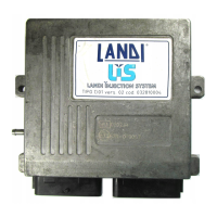
- an automotive type, weatherproof, 55-pin connector for
the connection to the ECU (Fig 3.7)
- a connector for the connection to the PC
- a connector for the working pressure tester
- a connector for the connection to the switch
- two connectors for the connection to the step-motors of
the proportioner.
Harness Description Table in the Figure 3.6:
Fig.3.7
Pin Signal Color
1. Ground Black
2. Petrol injection disabling Yellow
3. Cut-off solenoid valve Green/Black
4. 12V accessories Red
5. RPM counter Brown
6. Temperature Orange
7. N.C. N.C.
8. N.C. N.C.
9. Serial port +5V supply Red/White
10. Serial port ground Black
11. Serial port Data IN Pink/Black
12. Serial port Data OUT Pink
13. Pressure conn. supply Red/White
14. Pressure conn. signal Orange/Black
15. Pressure conn. ground Nero
16. N.C. N.C.
17 N.C. N.C.
18. N.C. N.C.
19. N.C. N.C.
20. N.C. N.C.
21. N.C. N.C.
22. N.C. N.C.
23. N.C. N.C.
24. N.C. N.C.
25. N.C. N.C.
26. N.C. N.C.
27. Proportioner Ground Black
28. +12 Battery Red/Black
29. Petrol injection disabling Yellow
30. N.C. N.C.
31. Gas out Blue
32. Oxigen sensor emulation Gris
33. Oxigen sensor Purple
34. Alternative fuel level sensor White
35. Power supply sensor Green
36. N.C. N.C.
37. N.C. N.C.
38. TPS Yellow/Blue
39. TPS/2 Blue/Black
40. Switch Brown
41. Switch shunter Blue
42. DC Switch supply Red
43. Switch Ground Black
44. Step motor signal White
45. Step motor signal Orange
46. Step motor signal Light blue
47. Step motor signal Purple
48. N.C. N.C.
49. N.C. N.C.
50. N.C. N.C.
51. N.C. N.C.
52. Step motor signal White
53. Step motor signal Orange
54. Step motor signal Light blue
55. Step motor signal Violette
Fig.3.6
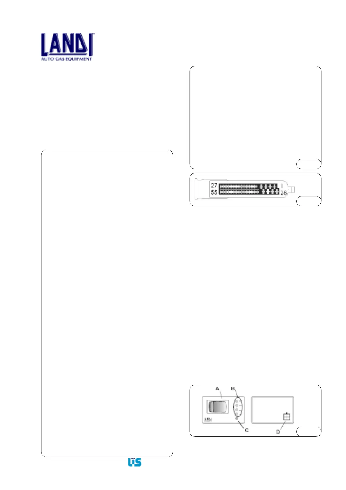
3.7 Switch
In the Figure 3.8 is reported the switch sketch.
3.7.1 Switch with fuel level indicator specifications
A) Gas-petrol switch, two positions
- switch in left, petrol position
- switch in right, gas position
B) Green L.E.D.s display bar readout interpretation:
- during the functioning of the vehicle in petrol, all LEDs
are OFF
- fast flashing, the system is waiting for automatic change-
over to gas after start-up. (please note that the start-up is
always on petrol);
- constantly on, the vehicle is operating on gas, the L.E.D.s
bar indicates the level of gas in the tank with a 1/4 tank
resolution;
- last L.E.D.(1/4) slow flashing, indicates reserve
condition.
C) Red L.E.D.
- the red L.E.D. slow flashing indicates gas system
malfunction.
D) Connector
- Connects the switch to the harness from the ECU.
Fig.3.8