Do you have a question about the Landis+Gyr E450 and is the answer not in the manual?
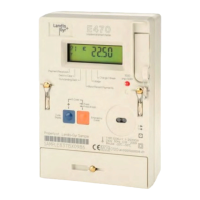
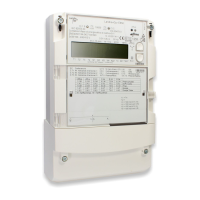
Offers a visual and functional overview of the E450 meter's capabilities.
Details the main features and specifications of the E450 meter.
Explains the coding system for meter configurations and variants.
Presents a block diagram of the meter's internal architecture and data flow.
Explains how signals are generated, converted, and processed within the meter.
Covers energy data storage, rate management, and relay output configuration.
Details disconnector control and introduces meter management software.
Explains hazard symbols, their meanings, and user responsibilities.
Lists essential safety rules to be followed during installation and operation.
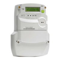
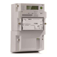
Describes the meter's housing, material, and the sliding cover's positions.
Details the components and labels on the meter's front faceplate.
Explains the function of the meter's display, disconnector, and reset buttons.
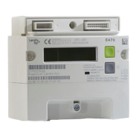
Provides physical dimensions and terminal connection details of the meter.
Illustrates typical wiring configurations for meter installation.
Covers intended environmental conditions and general installation prerequisites.
Details pre-installation checks, safety warnings, and meter mounting instructions.
Guides on positioning the suspension eyelet and drilling mounting holes.
Provides instructions for connecting phase and neutral wires to the meter terminals.
Details how to connect auxiliary inputs and relay outputs.
Outlines checks for correct wiring and initial meter operation procedures.
Explains how to navigate into the meter's service menu for configuration.
Details the submenu for configuring mains connection settings.
Details PLC menu options for communication status and configuration.
Explains the meaning of different PLC communication status codes.
Guides on the process of installing M-Bus devices via the meter.
Explains how to remove M-Bus devices from the meter configuration.
Details how to configure relays for normal or inverted operation.
Explains the structure and elements of the meter's LCD screen.
Describes symbols for energy direction, disconnector status, tampering, and units.
Covers the meter's display modes and how to navigate through them.
Details the default meter display mode and key interactions.
Explains how to access and navigate standard and MID data lists.
Lists the submenus and navigation within the service menu.
Details viewing service data and installing communication devices via menus.
Guides on manually setting the meter's time and date via the service menu.
Explains how to activate test mode and configure the test output LED.
Lists common display items and their corresponding OBIS codes.
Details the various operating modes for the disconnector control.
Provides information on meter service and initial steps for resolving operational issues.
Explains the format and structure of error codes displayed by the meter.
Provides detailed explanations for critical error codes and their causes.
Details errors related to communication, memory, and system functions.
Outlines procedures for the proper disposal of the meter as electronic waste.
| Type | Electricity Meter |
|---|---|
| Display | LCD |
| Communication | M-Bus |
| Voltage | 230V |
| Frequency | 50 Hz |
| Mounting | DIN rail |
| Current | 5(60)A |
| Storage Temperature | -40°C to +70°C |