Do you have a question about the Landis+Gyr ZMQ202 and is the answer not in the manual?
Manual applies to specified meters.
Contains information required for meter application.
Intended for technically qualified personnel.
Explains conventions for meter type names.
Draws attention to danger levels and pictographs.
Describes intended uses of the ZxQ meter.
Outlines responsibilities of meter owner and personnel.
Lists essential safety rules to be observed.
Highlights key features and benefits of the ZxQ meter.
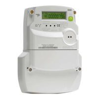
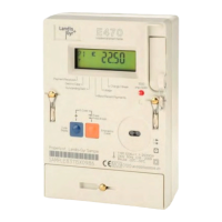
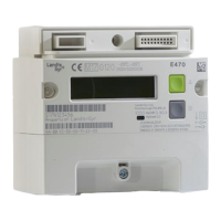
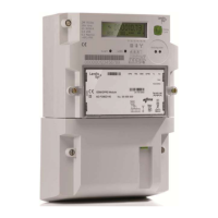
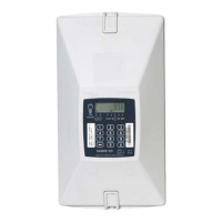
Visual representation of meter components and connections.
Details available input signals like voltage and current.
Lists meter outputs like LCD, LEDs, and interfaces.
Identifies analogue input signals for current and voltage.
Explains voltage and current input circuit operations.
Describes conversion of analogue signals to digital values.
Details calculation of digital raw data by the signal processor.
Lists measured quantities calculated by the microprocessor.
Lists measured quantities for netenergy function.
Lists measured quantities for enerflex function.
Explains calculation of active and reactive energy.
How reactive energy is allocated to four quadrants.
How to adjust clock using sync signal.
Describes clock adjustment at regular intervals.
Describes clock adjustment once daily.
How to adjust clock via central station.
Explains effects of time deviation on clock adjustment.
Describes saving register statuses to load profile.
Explains storage of sporadic events.
Illustrates components of wall-mounting setup.
Illustrates components of rack-mounting setup.
Details sealing types for wall and rack mounting.
Explains securing of meter after assembly and testing.
Explains securing after measuring capability verification.
Details seals applied after preparation for use.
Details the face plate behind the front window.
Details the information plate on the hinged front door.
Specifies meter connection on the back of the face plate.
Details plates on the front cover for f9 mounting.
Specifies meter connection on the top of the case.
Shows physical dimensions for f6 mounting.
Shows physical dimensions for f9 mounting.
Instructions for mounting the f6 meter.
Lists essential requirements before installation.
Details the terminal connection diagram for f6.
Shows the terminal layout for f6 connectors.
Step-by-step instructions for connecting f6.
Details the plug connection diagram for f9.
Shows the terminal layout for f9 connectors.
Step-by-step instructions for connecting f9.
Procedures to verify correct installation.
Instructions for setting meter date and time.
Instructions for setting battery low indicator.
Step-by-step instructions for disconnecting f6.
Step-by-step instructions for disconnecting f9.
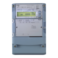
Identifies physical controls and indicators on the meter.
Explains the LCD display and its segments.
Explains OBIS code structure for data identification.
Details functions of Up and Down buttons.
Describes interface for data readout and setting.
Explains green optical outputs for testing.
Explains the red LED indicating meter malfunction.
Guides selection of different display views.
Describes viewing certified values in lists.
Details how to view recorded load profile data.
Explains how to access and interpret event log entries.
How to view saved register values.
Information on loss measurement availability.
How to access grid diagnostic information.
Meter use in production/transmission networks.
Lists various communication methods.
Describes different communication unit types.
Explains the MAP 120 tool's lifecycle support.
Location and functions of the alarm reset button.
Overview of the meter's service menu structure.
Steps to navigate the service menu.
How to access and view service list entries.
Accessing and viewing installation diagnostics.
How to select measuring values for optical test output.
Setting the battery low indicator on/off.
Identifies errors preventing measurement function.
Describes internal meter errors affecting data accuracy.
Details internal/external conditions causing indications.
Periodic accuracy checks according to standards.
Selects values for optical test output.
Procedure for testing meter at no load.
Procedure for testing with starting active load.
Procedure for testing with starting reactive load.
Procedures for changing the battery.
Conditions indicating battery replacement.
Step-by-step guide for battery replacement.
Reasons for changing the communication unit.
Procedures for changing the communication unit.
Steps for f6 meter.
Steps for f9 meter.
Guidelines for disposing of meter components.
Guidelines for disposing of the meter as a complete unit.
| Voltage | 230V |
|---|---|
| Frequency | 50Hz |
| Mounting | DIN Rail |
| Display | LCD |
| Operating Temperature | -25°C to +55°C |