Do you have a question about the Landis+Gyr E650 Series and is the answer not in the manual?
Specifies which meters the user manual applies to and outlines its content and intended use.
Identifies the qualified personnel for whom the manual is intended.
Lists related technical documentation and explains conventions used in type designations.
Details where ZxD400xT meters can be used across different voltage levels.
Lists the fundamental features and capabilities of the ZxD400xT meter series.
Explains the structure and meaning of the meter's type designation codes.
Illustrates the internal functional blocks and data flow of the ZxD400xT meter.
Covers the meter's input signals, signal processing, and measured quantities.
Describes memory storage for billing values, load profiles, and event logs.
Details optical interface and various communication units for data transfer.
Describes software tools for meter parameterization, testing, and service.
Details security features like magnet detection and terminal cover monitoring.
Explains safety symbols, danger levels, and general precautions.
Outlines responsibilities for safe meter installation, operation, and personnel training.
Lists essential safety rules to be observed during meter installation and operation.
Discusses potential radio interference and necessary user precautions.
Describes the sealing mechanisms and utility seals used to secure the meter.
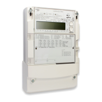
Details the main and tariff face plates and their components.
Explains the terminal blocks and meter connection diagrams.
Provides example connection diagrams for different meter configurations and networks.
Provides physical dimensions of the meter with standard terminal cover.
Provides general guidance and recommendations for meter connection across voltage levels.
Details connection methods for medium and high voltage using Aron circuits.
Describes connections for high voltage using three-phase four-wire circuits.
Provides instructions and safety precautions for physically installing the meter.
Details procedures for making electrical connections, including specific interfaces like RS485.
Emphasizes verifying all connections are correct before operation.
Outlines steps for putting the meter into service and performing initial checks.
Provides instructions for installing the terminal cover detection feature.
Describes the procedure and safety precautions for removing the meter.
Explains how the meter operates using an auxiliary supply during power cuts.
Describes the physical buttons and optical interface for controlling meter display and functions.
Explains the LCD layout, symbols, and display elements.
Details the index system used for displaying data, including OBIS codes.
Describes the three display modes: operating, menu, and service.
Explains how to navigate through the display menus and access data.
Details how to access and navigate the meter's service menu.
Explains the function and triggers for the meter's alert LED.
Describes the optical outputs used for meter testing and pulse transmission.
Explains methods for reading meter data via display, IEC 62056-21, or DLMS protocols.
Lists commands for modifying meter data and characteristics.
Guides users on changing meter settings like date, time, and identification numbers.
Provides initial checks for common meter operational issues.
Explains meter error codes, their structure, groups, and classifications.
Outlines the procedure for sending meters for repair to an authorized service center.
Describes periodic meter testing procedures, including test modes and measuring times.
Explains the use of optical outputs for meter testing and how to interpret the pulses.
Covers Creep Test, Starting Test Active Part, and Starting Test Reactive Part procedures.
Provides instructions and conditions for replacing the meter's battery.
Outlines regulations and methods for disposing of meter components responsibly.
| Model | E650 Series |
|---|---|
| Manufacturer | Landis+Gyr |
| Display | LCD |
| Type | Electricity Meter |
| Frequency | 50/60Hz |
| Communication | RS485, PLC |
| Standards | IEC 62053-21, IEC 62052-11 |
| Current | 5-100A |