Installation Procedure Installation
2-
2
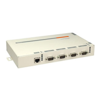
Five LEDs are located on the top of the unit. The following table explains their functions.
Note:
Although a red LED during boot mode usually signals an error, red
LED patterns are part of the normal operation of the MSS and are not
necessarily indicative of errors or dangerous operation.
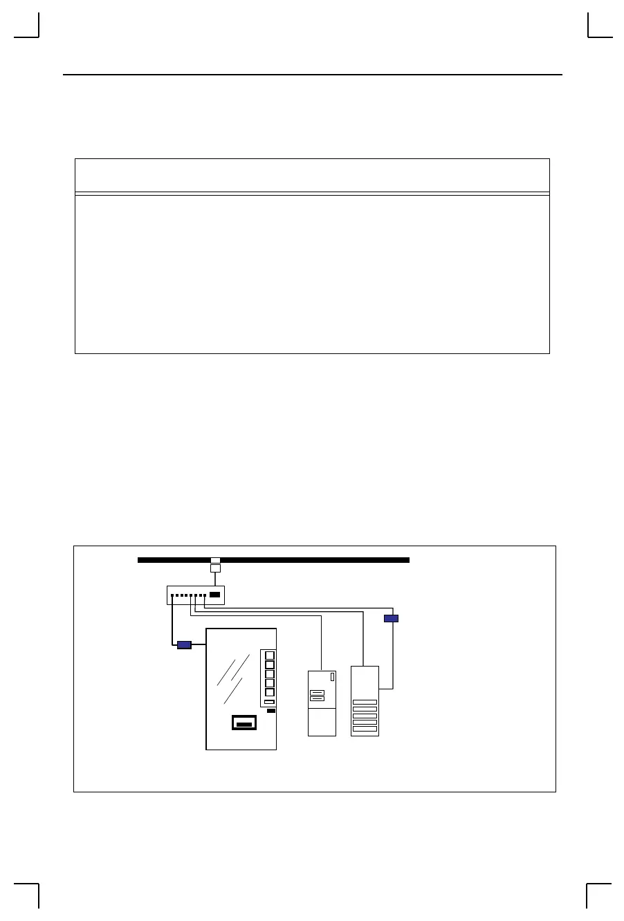
2.2 Installation Procedure
The MSS can be used to network-enable serial devices as shown in the figure below. Any
device with a serial port can be connected to the network via an MSS.
Figure 2-3:
MSS Network Layout
Table 2-1:
MSS LEDs
LED Function
Power Glows green when power is supplied to the MSS
Link Glows green while the MSS is connected properly to a 10BASE-T or
100BASE-T Ethernet network
100 Glows green to indicate a 100BASE-T Ethernet connection
OK Blinks yellow, green, or red to indicate MSS activity.
Serial Blinks yellow, green, or red to indicate MSS activity.
10/100 Switch
MSS
Serial Device
Twisted Pair
File
Sun
console port
Server
Ethernet
MSS
 Loading...