Shenzhen Qilin Laser Application Technology Co., Ltd.
Laser control interface
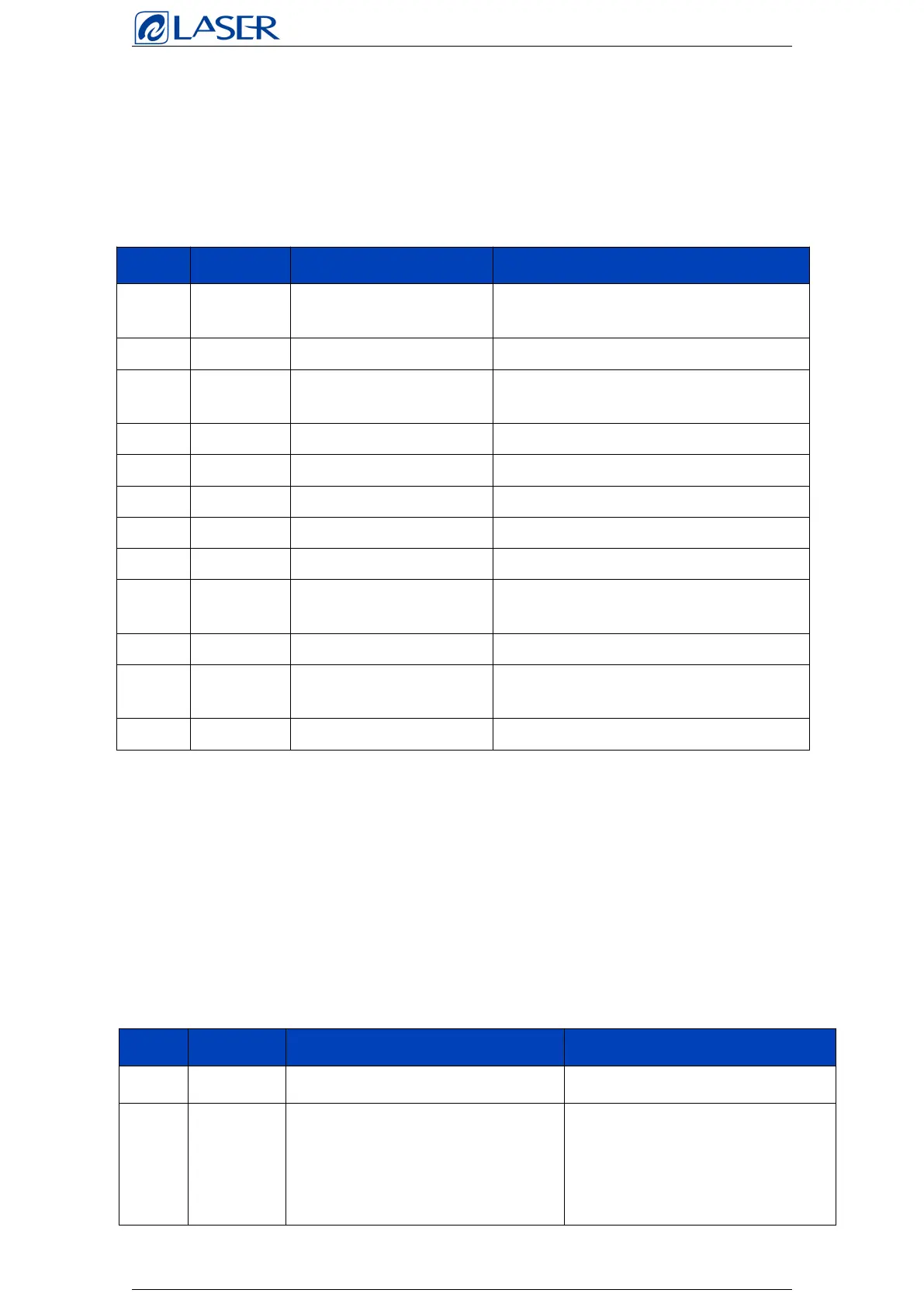
The laser interface is an 8 PIN green terminal +4PIN green terminal +RS232 interface.
* The table shows the definition of laser source interface.
Welding head interface
The mainboard provides a galvanometer port, which is compatible with
common digital galvanometer ports in the market.
* The table describes the galvanometer port definitions.
Duty cycle is adjustable from 1%-100%,
24V and 5V can be switched
Control laser signal, high level effective,
24V and 5V can be switched
Laser red light control (optional)
For laser peak power adjustment, 0-10V
and 0-4V analog voltage options
For proportional valve regulation, 0-10V
analog voltage
Galvanometer & OLED interface
Generally connected to the fire
button on the welding head, when
pressing the button on the gun,
the welding status light on the
7-inch screen will light up