Shenzhen Qilin Laser Application Technology Co., Ltd.
Gas control interface
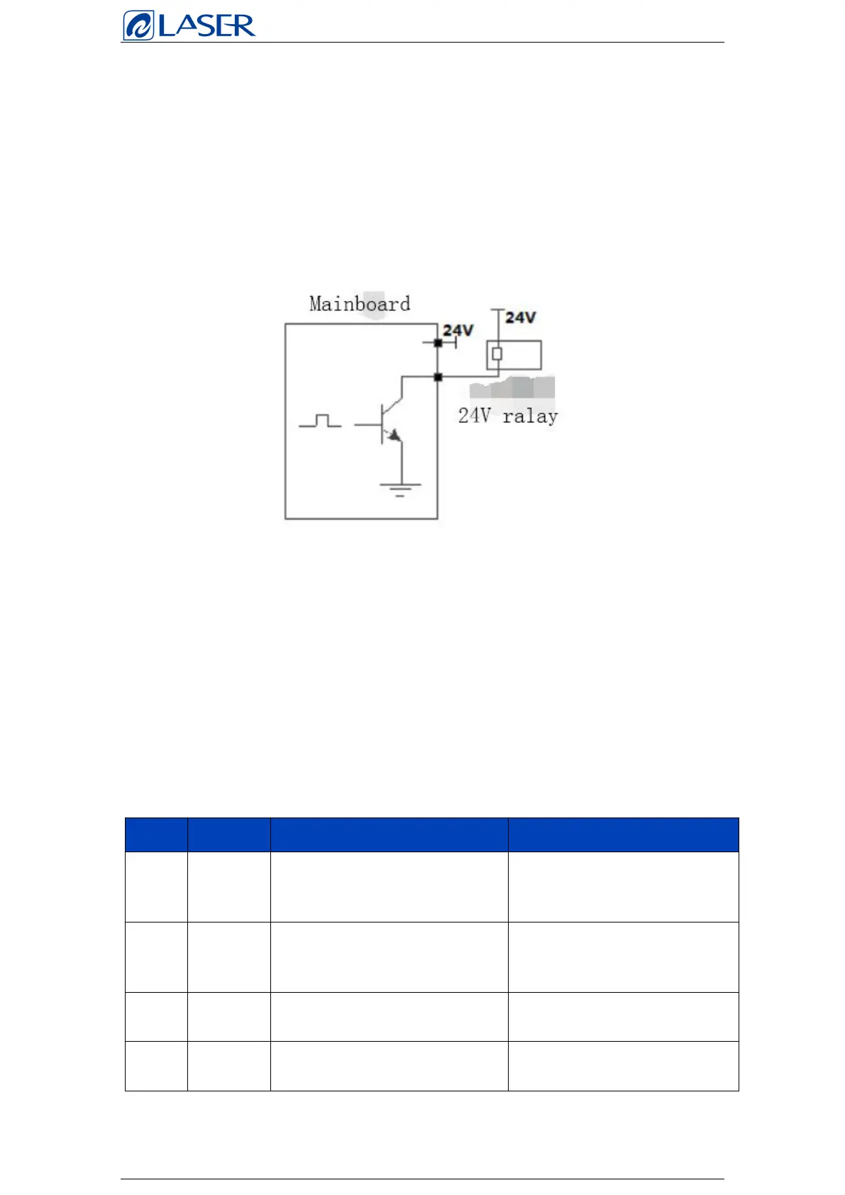
Control box provides a special IO interface, all output IO using OC output can
directly drive the relay, the maximum current up to 500mA, the wiring diagram
is as follows.
Wiring diagram of outlet relay
Feeder control interface
The control box provides a specified communication interface to control wire
feeder. 3A current can be provided after 24V power supply is directly connected
to the power input interface of the control box.
*The table shows the definition of the control interface of the wire feeder.
Used to protect the gas blowing
control, positive pole
Mainboad
control relay is
recommended
Used to protect the gas blowing
control, negative pole
Connect to
negative pole of
24V relay
Wire feeder trigger signal 1
Wire feeder
control signal
Wire feeder trigger signal 2
Wire feeder
control signal