EasyManua.ls Logo

Laser BWT15 - User Manual

Laser BWT15
14 pages
Print Icon
To Next Page IconTo Next Page
Loading...
Shenzhen Qilin Laser Application Technology Co., Ltd.
Hand-held Welding Head Manual
Model No.BWT15
Declaration
1. Shenzhen qilin laser application co., ltd. may update the operating instructions at
any time due to software or hardware upgrades. These updates will be included in the
new version of the operating instructions.Read the instructions carefully before using
the welding system !
2. Purchase Qilin laser handheld welding system to enjoy a lifetime of software
upgrade service, in the stipulated warranty scope, shenzhen qilin laser to fulfill the
promise of warranty service.It is strictly prohibited to disassemble or repair this
product by personnel other than our company without permission. In case of any
damage caused by the above factors, our company will not provide any free warranty
service.The company shall not be liable for any loss which may result from the use of
the product.The contents contained in the operating instructions shall not be modified
or reproduced by any organization or individual by any means. Shenzhen Qilin Laser
Application Technology Co., LTD has the right to interpret the product description.
Question and Answer IconNeed help?

Do you have a question about the Laser BWT15 and is the answer not in the manual?

Summary

Declaration

Security information

Technical parameters

Operating instruction

Control Section for Screen

Laser Control

Controls power, frequency, and duty cycle for laser output.

Motor Control

Manages motor speed, wobble width, and working modes.

Gas Control

Power Setting for slowly rising & falling

Position Setting for Red Light

Multi-language and Lock Settings

Connection Definition

Controller Connection

Diagram showing connections for the controller unit.

Power Interface

HMI

Laser control interface

Welding head interface

Gas control interface

Feeder control interface

Safety clamp interface

DIP switch

NOTICE

Service

Overview

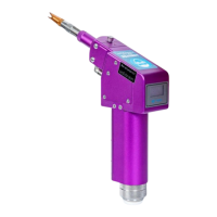
This document outlines the features, specifications, and operational guidelines for the Hand-held Welding Head, Model No.: BWT15, manufactured by Shenzhen Qilin Laser Application Technology Co., Ltd.

Function Description:

The Hand-held Welding Head is a component of a laser welding system designed for various welding applications. It integrates a laser control system, motor control for wobble functionality, and gas control to ensure precise and efficient welding. The system is designed for ease of use with a graphical user interface (GUI) that displays signal status and allows for parameter adjustments.

The core function of the device is to deliver a laser beam for welding. It supports different working modes, including a minimal spot mode for strong penetration, a swinging motor mode for adjusting mark width and energy density, and a dual-motor swinging mode for various beam shapes and thin plate welding. The system incorporates safety features such as a security lock signal that requires the welding torch nozzle to be in contact with the metal material for laser output.

The control box provides interfaces for various functions:

  • Laser Control: Manages the laser switch, power, frequency, and duty cycle. It includes analog output voltage controls for laser peak power adjustment and proportional valve regulation.
  • Motor Control: Adjusts the motor speed (frequency) and wobble size (width) to achieve desired welding patterns.
  • Gas Control: Manages gas flow, including advance/delay settings to protect the protective lens from welding dust, and proportional valve control for effective gas management.
  • Feeder Control: Provides a communication interface to control a wire feeder, with trigger signals for precise wire feeding.
  • Safety Clamp Interface: Ensures that the welding torch nozzle is in contact with the welding platform or materials before laser output, enhancing operational safety.
  • Red Light Positioning: Allows adjustment of the X and Y motor reflecting lenses to change the red light offset position, with an adjustment radius of 5mm for the laser center point.
  • Multi-language and Lock Settings: Supports multiple languages (Chinese, English, Russian, Korean, Vietnamese, Japanese) and includes features for displaying the serial number, controller version, available life (permanent use permission indicated by "-"), and license entry for locking/unlocking the machine.

The system also features power settings for slowly rising and falling laser power, which protects the protective lens and improves welding effectiveness. The rise and fall times can be adjusted from 20-400ms.

Important Technical Specifications:

  • Interface Type: QBH
  • Power Range: 2000W
  • Laser Wavelength: 1064-1080 nm
  • Wobble Width: 0.2-5.0 mm
  • Collimating Length: 50 (D20F50*3.5)
  • Focal Length: 150 (D20F50*3)
  • Protective Lens: D20X2
  • Cooling Way: Water
  • Weight: 1.2 kg
  • Working Mode: Three distinct modes are indicated by symbols: a single dot (minimal spot), a horizontal line (swinging motor), and a complex pattern (dual-motor swinging).

Control Box Electrical Interfaces:

  • ±15V Interface: Provides power for the motor drive.
    • V1 (Pin 1): +15V power input (current > 3A)
    • GND (Pin 2): Power ground
    • V2 (Pin 3): -15V power input (current > 3A)
  • DC24V Interface: Provides power for the control box internal control system.
    • 24V (Pin 1): +24V power input (current > 3A)
    • GND (Pin 2): Power ground
  • HMI Port: 5-pin green terminal for mainboard power supply and communication.
    • 24V (Pin 1): Output power, 500mA (HMI power supply)
    • GND (Pin 2): Power ground
    • TXD (Pin 3): HMI sender (Serial port communication TXD signal)
    • RXD (Pin 4): HMI receiver (Serial port communication RXD signal)
  • Laser Control Interface: 8-PIN green terminal + 4-PIN green terminal + RS232 interface.
    • PWM+ (Pin 1): MOD+ (Duty cycle 1%-100%, 24V/5V switchable)
    • PWM- (Pin 2): MOD- (Connectable to GND)
    • EN+ (Pin 3): Enable + (Control laser signal, high level effective, 24V/5V switchable)
    • EN- (Pin 4): Enable - (Connectable to GND)
    • RED+ (Pin 5): Red laser + (Laser red light control, optional)
    • RED- (Pin 6): GND (Connectable to GND)
    • NC+ (Pin 7): Enabled standby signal + (TBD)
    • NC- (Pin 8): GND (Connectable to GND)
    • DA 1+ (Pin 9): Analog output voltage+ (0-10V/0-4V options for laser peak power adjustment)
    • DA 1- (Pin 10): Analog output voltage- (Connectable to GND)
    • DA 2+ (Pin 11): Analog output voltage (0-10V for proportional valve regulation)
    • DA 2- (Pin 12): GND (Connectable to GND)
  • Welding Head Interface:
    • DB15 (Pin 1): Galvanometer & OLED interface (To connect welding head)
    • CF (Pin 2): Welding interface (Connects to fire button on welding head; welding status light on 7-inch screen illuminates when pressed)
  • Gas Control Interface: IO interface with OC output up to 500mA for driving relays.
    • CAS1+ (Pin 1): Positive pole for gas blowing control (Mainboard control relay recommended)
    • CAS1- (Pin 2): Negative pole for gas blowing control (Connect to negative pole of 24V relay)
  • Feeder Control Interface: Provides 3A current after 24V power supply connection.
    • SS_1 (Pin 3): Wire feeder trigger signal 1 (Wire feeder control signal)
    • SS_2 (Pin 4): Wire feeder trigger signal 2 (Wire feeder control signal)
  • Safety Clamp Interface:
    • DT (Pin 1): Security lock signal input (Must be connected to welding platform/materials; pilot signal on when nozzle is in contact with metal)
  • DIP Switch:
    • Left side: For IPG laser sources.
      • IPG (Pin 1): IPG Laser control signal (PWM, EN, RED, NC output 5V)
      • IPG (Pin 2): IPG LPC (Power adjustment: 0-4V analog voltage)
    • Right side: For other laser sources.
      • NO IPG (Pin 3): Laser control signal except IPG (PWM, EN, RED, NC output 24V)
      • NO IPG (Pin 4): LPC except IPG (Power adjustment: DA 1 analog voltage 0-10V)

Usage Features:

The system emphasizes user safety and correct operation through clear warnings and instructions. Users are advised to read the manual carefully before use.

  • Safety Precautions: Danger, Warning, and Caution signs indicate potential risks. Laser radiation labels are affixed to output products.
  • Software Upgrades: Lifetime software upgrade service is provided for Qilin laser handheld welding systems within the stipulated warranty scope.
  • Prohibition of Unauthorized Repair: Disassembly or repair by unauthorized personnel is strictly prohibited to maintain warranty validity.
  • Grounding: Effective grounding of handheld laser welding equipment is crucial to reduce leakage or static electricity.
  • Connection Verification: All bushing joints, laser head, and optical fiber connections must be properly connected, locked, and sealed with insulation tape to prevent dust ingress and ensure stability.
  • Water Seepage Check: Regular checks for water seepage in the cavity are necessary. Screws should not be loosened without professional training.
  • Lens Maintenance: Protective lenses should be cleaned with alcohol and a dust-free cloth at least five times when replaced. The replacement environment should be clean and wind-free.
  • Liquid Avoidance: The laser head is complex and must be kept away from water and liquids to prevent short circuits.
  • Cleaning: Only alcohol and a dust-free cloth should be used for cleaning; strong wind is not recommended.
  • Motor Handling: The digital motor should be handled gently to prevent failure.
  • System Gas Usage: When not in use, the system gas should be repeatedly used to blow air, discharging dust. The copper nozzle should be removed, sealed with sealing tape, and reinstalled for blowing air more than twice before use.
  • Power Supply: A continuous and reliable power supply is essential to prevent damage to the welding control system from interruptions.
  • External Safety Lock: The external safety lock operates at 24V high level. Short-circuiting it with the GND housing of the aviation plug or other components during installation may damage the power supply or main control board.

Maintenance Features:

The manual provides guidelines for maintaining the device and outlines warranty terms.

  • Warranty Period: 12 months from the date of delivery for Qilin products.
  • Hardware Maintenance: Free maintenance and labor cost (customer affords freight) for faults in hardware such as the system motherboard, motor drive, wiring, and main display screen during the warranty period.
  • Exclusions from Warranty:
    • All lens categories (collimating lens, focusing lens, reflecting lens, protective lens, seal ring, etc.) are not covered.
    • All pistol integral cases, brass nozzles, stainless tubing, wire feed brackets, etc., are not covered.
  • On-site Repairs: If repairs aboard are necessary, the customer is responsible for travelling expenses.
  • Software Updates: Shenzhen Qilin Laser Application Co., Ltd. may update operating instructions due to software or hardware upgrades, and these updates will be included in new versions of the instructions.
  • Content Interpretation: Shenzhen Qilin Laser Application Technology Co., LTD reserves the right to interpret the product description.

Laser BWT15 Specifications

General IconGeneral
BrandLaser
ModelBWT15
CategoryWelding Accessories
LanguageEnglish