This document describes the Laserline Compact Alarm system, including installation, operation, and technical specifications for models 989E, 988E, 989EES, 975E, and 974E.
Function Description
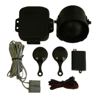
The Laserline Compact Alarm is a car alarm system designed to protect vehicles from theft and unauthorized access. It features a self-powered siren (for 989-975 models only) with an automatic internal battery power supply, which charges fully during the first 15 hours of operation and is then automatically controlled and maintained.
The alarm system incorporates several detection methods:
- Ignition Key Sensor: Triggers an alarm if an attempt is made to start the car.
- Shock Sensor: Detects impacts to the vehicle body.
- Boot/Bonnet/Doors Buttons: Triggers an alarm if protected areas (boot, bonnet, doors) are opened.
- Ultrasonics: Detects movement inside the vehicle.
- Drop in Voltage: Triggers an instantaneous alarm if a significant voltage drop (e.g., from bulb lighting) occurs.
- Cutting Supply Wires: For self-powered models, cutting the power wires will cause the alarm to activate.
The system also includes an engine immobilisation feature that becomes effective 20 seconds after the ignition is switched off (Passive Engine Stop). This function can be reset by turning the ignition key ON within 20 seconds. Once activated, the LED remains constantly ON, and the engine cannot be started. To cancel, turn the ignition key ON and push the central button. This function can be excluded by setting dip-switch n°4 to ON.
Anti-Code Grabbing with Variable Code Encryption:
The alarm uses a variable code encryption system to prevent "code-grabbing" by thieves. Each time a remote control button is pressed, a randomly generated digital code is transmitted. The system's microprocessor ensures that the same code is never sent or accepted twice, making code-grabbing ineffective.
Central Door Locking Connection:
The alarm system can be integrated with the vehicle's central door locking system, supporting various types:
- Negative Pole Type (Diagram 2/A): For vehicles with multi-point centralised door locks.
- Positive Pole Type (Diagram 2/B): For vehicles with multi-point centralised door locks.
- Control Only From One Position (Diagram 2/C): For vehicles with single-point centralised door locks.
- Control for Electro-Pneumatic Motor (Diagram 2/D): For vehicles with multi-point vacuum controlled central locking.
Usage Features
- Arming/Disarming: Signalled by two flashes of direction lights and two acoustic signals for arming, and one flash and one acoustic signal for disarming. This occurs via radio-control from up to 10 meters.
- Panic Function: Pressing the upper button on the remote activates the siren for 10 seconds. Pressing it again stops the siren.
- Casual Re-Arming: If the alarm is casually disarmed, it will re-arm itself if the driver's side door is not opened within 40 seconds. This function can be excluded by setting dip-switch n°4 to ON.
- Ultrasonic Exclusion (via remote control): Open the driver's side door, turn the ignition key ON, and push button n°1 on the remote. The LED flashes once, indicating exclusion. Re-establishment occurs automatically when the ignition key is switched ON.
- Ultrasonic and Window Closure Exclusion (via remote control): Open the driver's side door, turn the ignition key ON, and push button n°2 (panic) on the remote. The LED flashes twice, indicating exclusion. Re-establishment occurs automatically when the ignition key is switched ON. For 989EES models, arm the alarm with button n°1, then within 30 seconds, depress button n°2. This is signalled by one flash of indicator lights and one acoustic signal. Functions are restored when the alarm is disarmed.
- Siren Exclusion (via remote control - 989EES only): Turn the ignition key ON, push button n°2 on the remote. The red LED flashes once, indicating siren exclusion. Functions are restored when the alarm is disarmed.
- Emergency Override Switch (Security Key): In the OFF position, this key excludes all alarm functions and restores the engine immobilisation circuit, allowing the vehicle to be driven even if a fault is present.
Maintenance Features
- Self-Coding Remote Handsets: In case of a lost remote or the need for a new one, the installer can quickly re-code it. This involves disarming the alarm, turning the ignition ON, moving DIP switch No. 1 to ON, pressing the arm/disarm button on the new remote until the LED blinks, then coding the original remote (if applicable), repositioning DIP switch No. 1 to its original position, and finally turning off the ignition and testing. A maximum of 4 remotes can be added.
- Remote Battery Replacement: The remote battery should normally be replaced every 6-12 months.
- Re-synchronisation Procedure: After certain activities (e.g., battery change), it may be necessary to push the middle button of the remote until the LED is extinguished. Depressing the same button a second time will restore normal remote operation.
- Self-Diagnostic LED Functions: When the alarm is disarmed by radio control, the LED flashes indicate the cause of the last alarm condition:
- LED OFF: No alarm occurred.
- 1 FLASH/PAUSE: Voltage drop.
- 2 FLASHES/PAUSE: Ultrasonic detection.
- 3 FLASHES/PAUSE: Instantaneous push button (bonnet, boot).
- 4 FLASHES/PAUSE: Shock sensor.
- 5 FLASHES/PAUSE: Ignition key sensor.
- 6 FLASHES/PAUSE: Cutting supply wires.
Turning the ignition key ON or re-arming the alarm system by remote resets the diagnostic memory.
Important Technical Specifications
- Power Supply: 12V DC
- Current Draw (Alarm ON):
- 989-989EES-988: 23 mA
- 975-974: 16 mA
- Current Draw (Alarm OFF):
- 989-989EES-988: 13 mA
- 975-974: 13 mA
- Exit Delay: 40 seconds
- Max. Alarm Cycle Duration: 30 seconds
- Time Between Consecutive Alarms: 5 seconds
- Ultrasonic Sensor Frequency: 40 KHz
- Max. Blinker Relay Contact Capacity: 5+5 Ampere
- Max. Stop Engine Relay Contacts Capacity: 8 Ampere
DIP Switch Coding Table:
The system's functions can be configured using DIP switches:
- Dip-switch n°1 (Auto-Code Function): OFF = Deactivated, ON = Activated.
- Dip-switch n°2 (Volt Drop Sensing): OFF = Activated, ON = Deactivated.
- Dip-switch n°3 (Acoustic Tone): OFF = Activated, ON = Deactivated.
- Dip-switch n°4 (Casual Re-Arming and Automatic Stop Engine): OFF = Activated, ON = Deactivated.
- Dip-switch n°5 (Closure Function): OFF = Comfort Closing (1 second), ON = Comfort Closing Only (25 seconds).
- Dip-switch n°6 (Central Locking): OFF = Electric (1 second pulse), ON = Pneumatic (2 second pulse).
Installation Guidelines:
- Disconnect the battery negative pole before installation.
- Handle the central unit with care.
- Route wires away from interference sources (high tension coil, spark-plug wires).
- Fix ultrasonic sensors at the top of the right and left 'A' pillars, away from ventilation systems.
- Adjust ultrasonic and shock sensor sensitivity carefully to avoid false alarms.
- The LIGHT BLUE WIRE must ALWAYS BE CONNECTED to existing interior door contact earth switches (via diodes if necessary) to prevent accidental alarming and door locking.
- For vehicles with catalytic exhaust, it is advised to install engine immobilisation on the fuel pump and starter solenoid.
- Do not shorten or lengthen shielded wires on ultrasonic detectors or the aerial wire.
- Place the alarm in the engine compartment ensuring maximum practical protection from excess heat (85°C max).
- If possible, fit the unit in a vertical position for reasonable access to the emergency override switch.
- All electric connections must be soldered and insulated with heat-shrink sheathing or black insulating tape. Avoid "quick couple" connections.
The 989 range of products meets the requirements of EEC 95/54 (EMC) and EEC 95/56 directives concerning protection devices against unauthorised use of motor vehicles and ETS norms.