A3
A2
A2
A1
4.
3.
A3
A2
<
0,15 mm / m = OK
EN
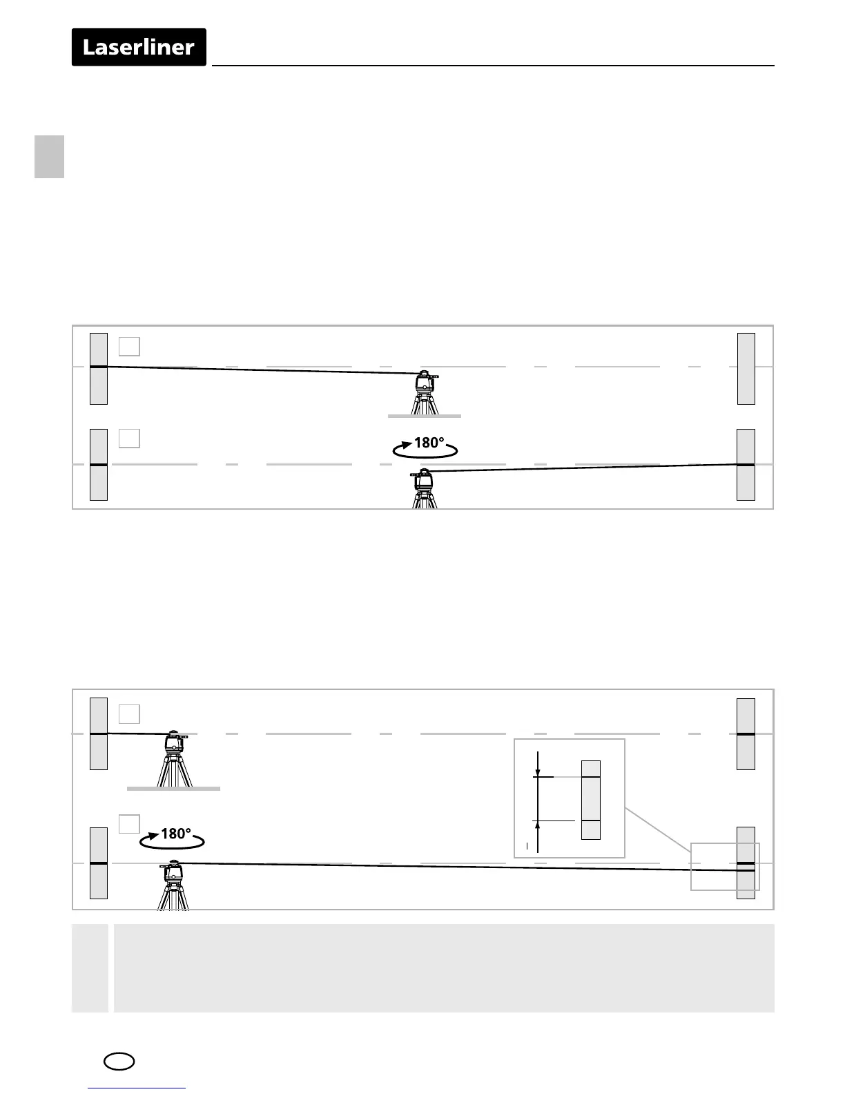
If points A2 and A3 are more than 0.15 mm / m apart on either
the X or Y axis, the device is in need of adjustment. Contact your
authorised dealer or else the UMAREX-LASERLINER Service Department.
!
Performing the calibration check
3. Position the device as near as possible to the wall at the height of point
A1. Now adjust the device in the X axis.
4. Turn the device through 180° and mark point A3. The difference between
points A2 and A3 is the tolerance for the X axis.
5. To check the Y and Z axis, repeat steps 3 and 4.
Preparing the calibration check
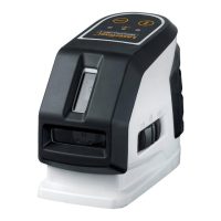
It is possible for you to check the calibration of the laser. To do this, position
the device midway between 2 walls, which must be at least 5 metres apart.
Switch the device on. The best calibration results are achieved if the device
is mounted on a tripod. IMPORTANT: The automatic sensor must be active
(auto/slope LED is off).
1. Mark point A1 on the wall.
2. Turn the device through 180° and mark point A2. You now have a
horizontal reference between points A1 and A2.