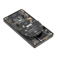
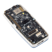
iCE40 UltraPlus 6:1 MIC Aggregation over SPI Demo
User Guide
© 2018 Lattice Semiconductor Corp. All Lattice trademarks, registered trademarks, patents, and disclaimers are as listed at www.latticesemi.com/legal.
All other brand or product names are trademarks or registered trademarks of their respective holders. The specifications and information herein are subject to change without notice.
2 FPGA-UG-02057-1.0
Contents
Acronymns in This Document ........................................................................................................................................ 3
1. Introduction .......................................................................................................................................................... 4
2. Functional Description ........................................................................................................................................... 4
2.1. Demo Design Overview ................................................................................................................................ 4
3. Demo Setup .......................................................................................................................................................... 5
3.1. Hardware Requirements ............................................................................................................................... 5
3.2. Software Requirements ................................................................................................................................ 5
3.3. Configuring the MDP Board .......................................................................................................................... 5
3.3.1. Setting Jumpers and Switches ................................................................................................................... 5
4. Programming the Demo ........................................................................................................................................ 7
4.1. Programming the Bitstream to the iCE40 UltraPlus MDP ............................................................................... 7
5. Running the Demo ................................................................................................................................................. 9
5.1. Using Windows Application .......................................................................................................................... 9
5.2. Oscilloscope Connection Points .................................................................................................................. 10
Appendix A. Schematic Diagram .................................................................................................................................. 11
Appendix B. Bill of Materials ........................................................................................................................................ 12
Technical Support ....................................................................................................................................................... 13
Revision History .......................................................................................................................................................... 13
Figures
Figure 2.1. iCE40 UltraPlus 6:1 MIC Aggregation over SPI Demo Overview ..................................................................... 4
Figure 2.2. iCE40 UltraPlus 6:1 MIC Aggregation over SPI Demo Block Diagram .............................................................. 4
Figure 3.1. iCE40 UltraPlus MDP Configuration .............................................................................................................. 5
Figure 3.2. 8 to 1 Mic Aggregator Board (Daughter Board) ............................................................................................. 6
Figure 3.3. iCE40 UltraPlus MDP and 8 to 1 Mic Aggregator Board ................................................................................. 6
Figure 4.1. Device Properties ......................................................................................................................................... 7
Figure 5.1. J30 Section on MDP Board ......................................................................................................................... 10
Figure 5.2. Header to Connect to the Oscilloscope ....................................................................................................... 10
Tables
Table 3.1. Detailed Information of the Board Configuration ........................................................................................... 6


 To Next Page