7.3 Configuring the interface
The inputs and outputs on the analog interface can be controlled using
either current values or voltage values. The following signaling parameters are
available:
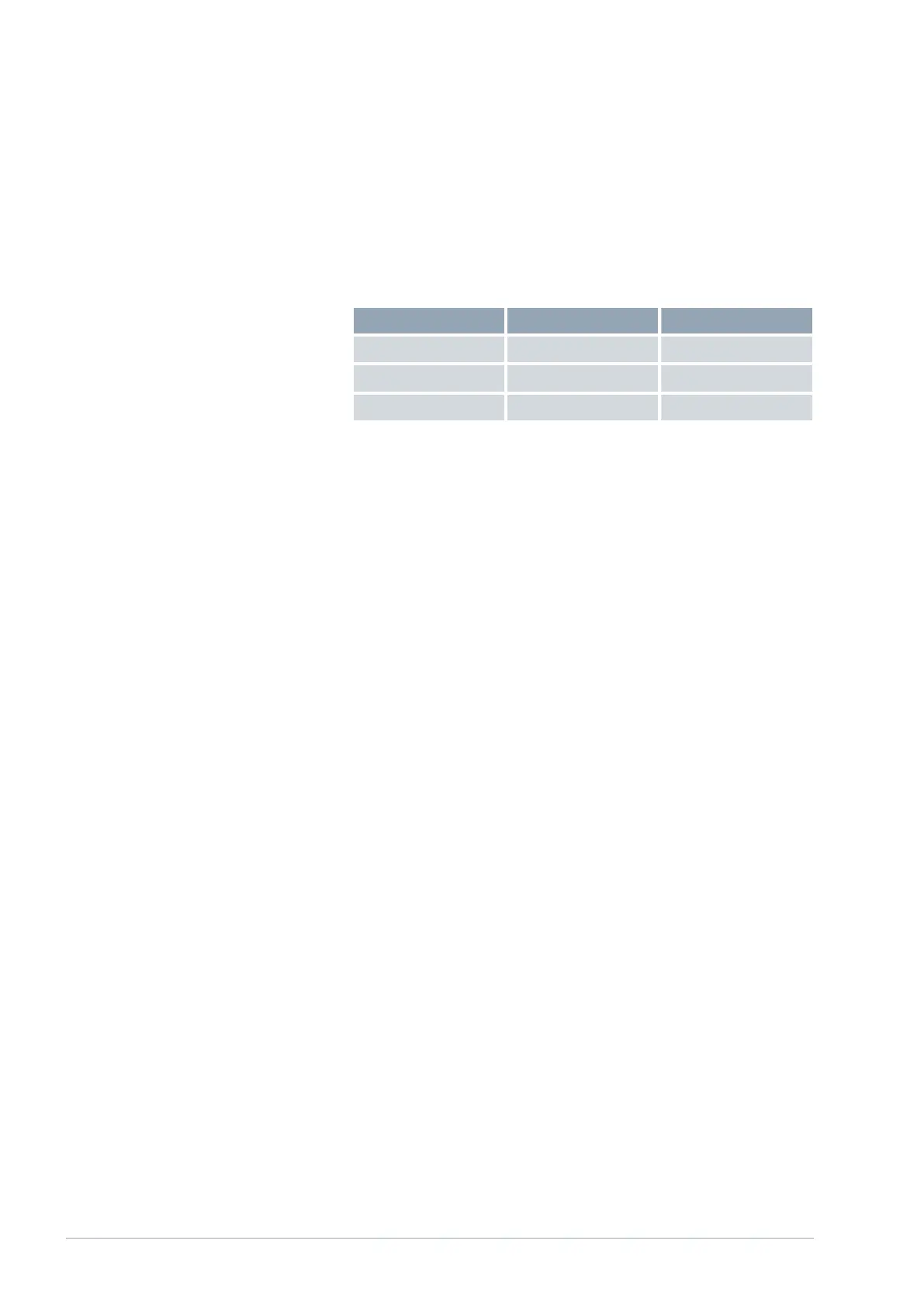
Signaling ( status ) Upper limit Lower limit
0 – 10 V 0 V 10 V
0 – 20 mA 0 mA 20 mA
4 – 20 mA 4 mA 20 mA
The inputs and outputs of the analog interface can be configured independ-
ently of one another. The signaling "4 – 20 mA" also allows the detection of
signal losses (decrease to 0 mA).
The working range of the selected function can be scaled freely by assigning
limit values accordingly:
Example: Analog input 1 with 0 – 20 mA signaling, set temperature function
Minimum value = 0 assigns the value 0 °C as the lower limit.
Maximum value
= 100 assigns the value 100 °C as the upper limit.
When this setting is selected, set temperatures between 0 and 100 °C can
be configured by changing the current value from 0 to 20 mA. For this
sample configuration, the following settings must be selected in the analog
interface menu:
Menu Analog interf. Analog input 1
1. Select the value Current 0 – 20 mA
for the Status parameter.
2. Select the value Set temperature for the Function parameter.
3. Enter the value 0 for the Minimum value parameter.
4. Enter the value 100 for the Maximum value parameter.
5. Configure all other settings in the same way.
V1
Interface module LRZ 91220 / 28