EasyManua.ls Logo

Launch TLT235SB - User Manual

Launch TLT235SB
17 pages
Print Icon
To Next Page IconTo Next Page
Loading...
LAUNCH Installation Instruction for Economical Symmetric Floor-plate 2-post Lift
i
Table of contents
1. Precaution………………………………………………1
2. Structure and working Principle.………………2
2.1 Structure Schematic Diagram…….……………………2
2.2 Main Structure and Principle of the Equipment...……3
3 Tools for installation and adjustment………………4
4. Unpacking…………………………………………….4
5. Installation…………….………………………………4
5.1 Important notice……………………………………4
5.2 Installation Procedure…………………………………4
5.2.1 Selecting installation site …………………………...4
5.2.2 Base plate layout……………………………………...5
5.2.3 Install the powerside column………………………….5
5.2.4 Install the floor plate…….………………………………6
5.2.5 Install the offside column………………………………6
5.2.6 Install and adjust the balancing steel cables………7
5.2.7 Install the power unit………………….…..………..…7
5.2.8 Connecting the power supply…………………………7
5.2.9 Connecting the hydraulic lines………………………...8
5.2.10 Install the swing arm and guardrail…………………..9
5.2.11 Adjust the steel chain…………………………………6
5.2.12 Install the floor plate cover…………………………9
6. Lift Adjustment……….……………………………….10
6.1 Preparation before adjustment……………………10
6.2 Adjustment procedure…………………………………10
7. List of the lift components………………………11
Diagram of the electrical system TLT235/TLT240SB...16
Diagram of the hydraulic system TLT235/TLT240SB…17
Question and Answer IconNeed help?

Do you have a question about the Launch TLT235SB and is the answer not in the manual?

Overview

This document provides installation instructions for the LAUNCH Economical Symmetric Floor-plate 2-post Lift, specifically models TLT235SB and TLT240SB.

Function Description

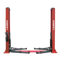
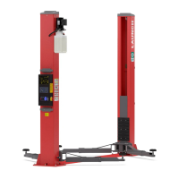
The LAUNCH Economical Symmetric Floor-plate 2-post Lift is designed for lifting vehicles to facilitate maintenance and repair. It operates on a hydraulic lifting mechanism, with each of the two columns housing a hydraulic cylinder. When the power unit is activated, hydraulic oil enters the lower chamber of the cylinders, forcing the piston rods upward and consequently raising the carriages via a chain system.

A key feature is its balancing mechanism, which employs two steel cables to interconnect the carriages. This ensures synchronous rising and descending, maintaining the carriages at an equal level from the floor. If the carriages or swing arms are not level, an adjustment screw at the end of the steel cable allows for equalization, ensuring the cables are tightly adjusted with equal tension to prevent damage.

The lift incorporates a manual safety locking system. Safety locking plates are installed on both carriages, engaging with a toothed bar plate welded to the internal wall of the column. During lifting, the safety locking plate moves up against the toothed bar plate. When the carriage stops, the plate engages a slot in the toothed bar, preventing the carriage from descending. To lower the carriage, it must first be raised slightly to disengage the safety locking plate, then the steel wire rope is manually pulled to release the lock, allowing the carriage to be lowered. This dual safety protection system requires pulling the steel ropes on both carriages to disengage the locks.

To prevent vehicle slip, the swing arms are equipped with a positioning mechanism that automatically locks during operation. The safety lock mechanism is effective for lifting pad heights ranging from 450mm to 1900mm.

Important Technical Specifications

Dimensions:

  • Passing width: 2486mm
  • Total width (A): 3370mm
  • Total height: 2750mm
  • Column spacing: 2610mm
  • Floor plate length: 2770mm
  • Minimum lifting pad height: 110mm
  • Diagonal line (C): 3410mm
  • Base plate width (B): 520mm (235mm + 235mm + 50mm)
  • Anchor bolts: 10 sets of M18×160
  • Drill bit diameter for anchor bolts: 19mm

Power Supply:

  • Single-phase motor: AC220V
  • Three-phase motor: AC380V
  • Power supply switch: AC500V, 20A (prepared by user)

Hydraulic System:

  • Hydraulic oil capacity: 10L
  • Recommended hydraulic oil: N32 or N46

Concrete Floor Requirements:

  • Minimum concrete slab thickness: 250mm
  • Minimum curing time for concrete slab: 20 days
  • Concrete slab must be reinforced with steel bars and leveled.
  • Foundation concrete intensity: above 3000PSI (2.1Kg/mm²)

Usage Features

Lifting Operation:

  • To raise the carriage, press the start button on the motor. Releasing the button stops the carriage.
  • For vehicle repair, once the desired height is reached, press the oil release handle to engage the mechanical safety lock, ensuring safety.

Lowering Operation:

  • To lower the carriage, first slightly raise it by pressing the start button to disengage the safety locks.
  • Then, pull the steel ropes on both carriages to release the safety locks.
  • Finally, press the manual lowering handle on the power unit to lower the carriage.

Swing Arms:

  • Two-stage telescopic swing arms allow adjustment to position the lifting pads at the correct lifting points of the vehicle.
  • Screw height below the pad can be adjusted to adapt to different vehicle chassis heights.
  • Swing arms automatically lock during operation to prevent vehicle slip.

Installation Site Selection:

  • Requires a stable, horizontal concrete floor. Slight slopes can be corrected with shimming.
  • Avoid asphalt or other non-concrete surfaces.
  • Sufficient space around the lift is necessary for unrestricted operation and to accommodate vehicles.
  • Avoid extreme temperatures, humidity, heating equipment, water taps, air humidifiers, or stoves.
  • Do not install in direct sunlight; use curtains if unavoidable.
  • No overhead obstructions (heaters, building supports, electrical pipes) in the installation area.
  • The front and back of the lift should have sufficient space for vehicles.

Maintenance Features

Manual Availability:

  • This manual is an essential part of the equipment and should be kept for use during maintenance.

Lubrication:

  • Lubricate the contact surface of the carriage and column corners with general-purpose lithium grease. All sliding surfaces should be evenly coated from top to bottom.
  • During installation, lubricate the moving parts of the swing arm and carriage to ensure free movement.

Hydraulic System Maintenance:

  • Fill the hydraulic oil reservoir with N32 or N46 hydraulic oil.
  • After new installation, the hydraulic system may contain air. To bleed air, repeat lifting and lowering cycles several times.
  • Ensure all hydraulic fittings are tightened to prevent oil leakage.
  • Operate carefully when filling hydraulic oil to avoid dust and pollutants.

Electrical System Maintenance:

  • All electrical wiring and connections must be performed by a certified electrician.
  • A power supply switch should be installed near the lift for convenient disconnection during maintenance or emergencies.
  • Ensure the oil tank is full before operation; operating without oil can damage the motor.
  • If the motor doesn't run, or abnormal noise/heat occurs after pressing the start button, immediately stop the machine and check electrical connections.

Cable Adjustment:

  • The balancing steel cables should be checked and adjusted for uniform tension to ensure synchronous movement of the carriages.
  • Ensure steel cables remain in the pulley during adjustment to prevent damage.

Chain Adjustment:

  • The steel chain is factory-adjusted to allow free movement of the swing arm at the lowest height without scratching the ground.
  • Fine adjustment of the chains can be made after electrical and hydraulic installation. To adjust, lift the carriage to a high position, lower for 2 seconds to engage the safety lock, then adjust the nut on the threaded end of the chain.

Installation Checks:

  • Before operation, re-check balancing steel cables for correct installation and ensure they are in the pulley.
  • Check for tightness of all connecting bolts.
  • Carefully check the packing list upon receipt for any shipment damage and completeness of parts.

Safety Precautions:

  • Personnel performing installation and adjustment must have electrical knowledge, special training, and qualifications.
  • Wear safety goggles and use hard alloy drill-bits during drilling.
  • Do not use drill-bits with excessive wear.
  • Do not ream holes or allow the drill to wobble during concrete drilling.
  • Use proper tools to remove dust from drilled holes.
  • Only use a torque wrench for fastening anchor bolts; do not use impact tools.
  • Ensure the column is vertical by inserting shims under the base plate if necessary (shims thickness not exceeding 5mm).
  • If the lift is used outdoors, a cover on the power unit is recommended to prevent damage from water or other liquids, which is not covered by warranty.

Launch TLT235SB Specifications

General IconGeneral
BrandLaunch
ModelTLT235SB
CategoryLifting Systems
LanguageEnglish

Related product manuals